
 Tìm kiếm
Tiêu chuẩn quốc gia TCVN 7336:2021 về Phòng cháy và chữa cháy - Hệ thống chữa cháy tự động bằng nước, bọt - Yêu cầu thiết kế và lắp đặt
| Số hiệu: | TCVN 7336:2021 | Loại văn bản: | Tiêu chuẩn Việt Nam |
| Nơi ban hành: | Các cơ quan khác | Người ký: | *** |
| Ngày ban hành: | Năm 2021 | Ngày hiệu lực: | *** |
| Lĩnh vực: | Tài nguyên - Môi trường, Xây dựng - Đô thị | Tình trạng: | Còn hiệu lực |
| ICS: | *** |
TÓM TẮT VĂN BẢN
Văn bản tiếng việt
 Tiêu chuẩn quốc gia TCVN 7336:2021 (Bản Word)
Văn bản tiếng anh
Phân loại cơ sở theo nhóm nguy cơ phát sinh cháy phụ thuộc vào công năng và tải trọng cháy
|
Nhóm nguy cơ phát sinh cháy |
Danh sách các cơ sở đặc trưng, ngành công nghiệp và quy trình công nghệ |
|
1 |
- Nhà văn phòng, làm việc; - Nhà ở: nhà chung cư, nhà tập thể, ký túc xá; - Trường học: nhà trẻ, trường mẫu giáo, mầm non; trường tiểu học, trung học cơ sở, trung học phổ thông, trường nhiều cấp học; trường đại học và cao đẳng, trường trung học chuyên nghiệp; trường dạy nghề, trường công nhân kỹ thuật, trường nghiệp vụ và các loại trường hoặc trung tâm đào tạo khác; - Bệnh viện, phòng khám (đa khoa, chuyên khoa), trạm y tế, nhà hộ sinh, nhà điều dưỡng, phục hồi chức năng, chỉnh hình, nhà dưỡng lão, cơ sở phòng chống dịch bệnh, cơ sở nghiên cứu, thí nghiệm chuyên ngành y tế, trung tâm y tế, cơ sở y tế khác; - Khu vui chơi, giải trí, thẩm mỹ, kinh doanh xoa bóp; - Nhà hàng, cửa hàng ăn uống, giải khát, tiện ích; - Khách sạn, nhà khách, nhà nghỉ, nhà trọ; - Bảo tàng, thư viện, triển lãm, nhà trưng bày, nhà sách, nhà hội chợ; - Nhà thể dục, thể thao; - Nhà ga hành khách (hàng không, đường sắt), nhà chờ bến xe ô tô, trạm dừng nghỉ, bến tàu, nhà chờ cáp treo. |
|
2 |
Tải trọng cháy 181-1400 MJ/m2. - Cơ sở kinh doanh karaoke, vũ trường, quán bar, câu lạc bộ; - Nhà hát, rạp chiếu phim, rạp xiếc, trung tâm hội nghị, tổ chức sự kiện, nhà văn hóa; - Chợ, trung tâm thương mại, siêu thị, cửa hàng; - Bưu điện, bưu cục, đài phát thanh, truyền hình, viễn thông, nhà lắp đặt thiết bị thông tin, trung tâm lưu trữ, đài kiểm soát không lưu; - Nhà ga hàng hóa (hàng không, đường sắt), nhà chứa máy bay, nhà chứa tàu điện, tàu hỏa; - Nhà để xe, nhà đăng kiểm, sửa chữa, bảo dưỡng ô tô, mô tô, xe gắn máy, xe điện; - Các gian phòng sản xuất của ngành công nghiệp chế biến gỗ; - Các gian phòng sản xuất của ngành công nghiệp thuốc lá; đồ điện tử (ti vi, máy tính, điện thoại...), điện lạnh (điều hòa, tủ lạnh,...); linh kiện, phụ tùng thông tin và điện tử (mạch in điện tử, IC và các sản phẩm tương đương); thuốc và vật tư y tế; pin, ắc-quy. - Các gian phòng sản xuất có quy trình sơn, ngâm tẩm, pha trộn, tẩy dầu mỡ, bảo quản và tái bảo quản, rửa các bộ phận với việc sử dụng chất lỏng và dầu mỡ dễ cháy; sản xuất len, vật liệu nhân tạo và phim; ngành may mặc; sản xuất có sử dụng sản phẩm cao su; cơ sở thuộc hạng nguy hiểm cháy nổ C3; - Các gian phòng sản xuất của nhà máy chế tạo máy động lực và máy nông nghiệp; nhà máy chế tạo máy công cụ và thiết bị công nghiệp; nhà máy chế tạo thiết bị nâng hạ; nhà máy chế tạo máy xây dựng; nhà máy chế tạo thiết bị toàn bộ; nhà máy sản xuất, lắp ráp phương tiện giao thông (ô tô, xe máy, tàu thủy,...); nhà máy chế tạo thiết bị điện, thiết bị cơ cho công nghiệp điện tử, điện lạnh; nhà máy sản xuất các sản phẩm cơ khí cho các ngành công nghiệp khác (công nghiệp hỗ trợ) - Băng tải vận chuyển nguyên vật liệu dễ cháy; - Các gian phòng xay xát, lau bóng gạo; sản xuất, chế biến, đóng gói các sản phẩm nông sản khác. |
|
3 |
- Phòng để sản xuất các sản phẩm cao su; - Phòng để sản xuất bột giấy và giấy; xơ sợi; dệt; in, nhuộm (ngành dệt, may); sản phẩm may; thuộc da và các sản phẩm từ da; các sản phẩm nhựa |
|
4.1 |
Tải trọng cháy 1401-2200 MJ/m2 Phòng để sản xuất sợi tự nhiên và tổng hợp dễ cháy, buồng sơn và sấy khô, khu vực sơn hở và sấy khô, sơn, vecni và các cơ sở làm keo sử dụng chất lỏng cháy và chất lỏng dễ cháy |
|
4.2 |
Tải trọng cháy trên 2200 MJ/m2 Phòng máy của trạm nén khí, thu hồi, hydro hóa, trạm chiết xuất và các cơ sở sản xuất khác sử dụng khí cháy, xăng, cồn và các loại chất lỏng cháy và chất lỏng dễ cháy khác và cơ sở thuộc hạng nguy hiểm cháy nổ C1 |
|
5 |
Kho chứa vật liệu không cháy trong bao bì dễ cháy. Kho vật liệu dễ cháy |
|
6 |
Kho chứa vật liệu dễ cháy bao gồm cao su, nhựa... |
|
7 |
Kho vecni, sơn, chất lỏng dễ cháy, chất lỏng cháy |
CHÚ THÍCH 1: Nhóm các cơ sở được xác định theo công năng của chúng. Trong trường hợp không thể chọn cơ sở tương tự thì xác định nhóm theo công năng của các gian phòng.
CHÚ THÍCH 2: Nhóm của các cơ sở được xác định theo tải trọng cháy.
CHÚ THÍCH 3: Các thông số của hệ thống chữa cháy bằng nước và bọt cho các phòng kho trong các tòa nhà, cơ sở thuộc nhóm nguy cơ phát sinh cháy nhóm 1 được lấy theo các phòng thuộc nhóm nguy cơ phát sinh cháy nhóm 2.
CHÚ THÍCH 4: Đối với nhóm nguy cơ phát sinh cháy nhóm 2, lưu lượng và cường độ phun nước hoặc dung dịch chất tạo bọt phải được tăng lên so với các giá trị tiêu chuẩn được đưa ra trong Bảng 1 cho nhóm nguy cơ phát sinh cháy nhóm 2, không nhỏ hơn:
- 1,5 lần khi tải trọng cháy trên 1400 MJ/m2;
- 2,5 lần khi tải trọng cháy cụ thể trên 2200 MJ/m2.
Phương pháp tính toán các thông số của hệ thống chữa cháy theo bề mặt với chất chữa cháy là nước hoặc bọt bội số nở thấp
B.1 Thuật toán để tính toán các tham số của hệ thống chữa cháy tự động bằng nước và bọt bội số nở thấp
B.1.1 Loại chất chữa cháy (nước hoặc dung dịch chất tạo bọt) được chọn tùy thuộc vào loại đám cháy.
B.1.2 Căn cứ nguy hiểm cháy và tốc độ lan truyền của đám cháy để lựa chọn loại hệ thống chữa cháy Sprinkler hoặc Drencher hoặc Sprinkler-Drencher hoặc tổ hợp của các hệ thống.
CHÚ THÍCH: Trong phụ lục này, trừ khi có quy định khác, đầu phun được hiểu chung là đầu phun nước và bọt.
B.1.3 Loại hệ thống Sprinkler (ướt hoặc khô) được lựa chọn phụ thuộc vào nhiệt độ vận hành của hệ thống.
B.1.4 Nhiệt độ tác động danh định của đầu phun được xác định theo nhiệt độ môi trường xung quanh khu vực bố trí đầu phun.
B.1.5 Cường độ phun, lưu lượng, diện tích phun tối đa, khoảng cách giữa các đầu phun và thời gian phun được lấy theo nhóm nguy cơ phát sinh cháy của đối tượng được bảo vệ (theo Phụ lục A và Bảng 1, 2, 3)
B.1.6 Lựa chọn loại đầu phun phải phù hợp với lưu lượng, cường độ phun và diện tích được bảo vệ bởi nó, cũng như các giải pháp kiến trúc và bố trí mặt bằng của khu vực được bảo vệ.
B.1.7 Sơ đồ nguyên lý mạng đường ống và mặt bằng vị trí bố trí đầu phun để làm rõ và xác định mạng đường ống đến đối tượng được bảo vệ phải được thể hiện dưới dạng sơ đồ không gian (không bắt buộc phải theo tỷ lệ).
B.1.8 Khu vực để tính toán của hệ thống phải được đánh dấu trên sơ đồ tại vị trí bố trí đầu phun chủ đạo.
B.1.9 Tính toán thủy lực của hệ thống chữa cháy phải thực hiện:
- Áp suất yêu cầu tại đầu phun chủ đạo được xác định theo cường độ phun, cao độ của đầu phun trong mạng đường ống và khoảng cách giữa các đầu phun.
- Đường kính ống được thiết kế cho các phần khác nhau của mạng đường ống phải đảm bảo vận tốc của nước và dung dịch chất tạo bọt trong đường ống không vượt quá 10 m/s và không quá 2,8 m/s trong ống hút; đường kính của đường ống hút được xác định bằng tính toán thủy lực liên quan tới họng hút của máy bơm chữa cháy được sử dụng;
- Phải tính toán lưu lượng của mỗi đầu phun trong khu vực tính toán của hệ thống (có tính việc lưu lượng của các đầu phun được lắp đặt trên mạng phân phối tăng theo khoảng cách đến đầu phun chủ đạo) và tổng lưu lượng của các đầu phun tại khu vực tính toán.
- Phải kiểm tra, tính toán mạng đường ống của hệ thống trong trường hợp nhiều đầu phun kích hoạt, khi tổng lưu lượng và cường độ phun trong khu vực tính toán không nhỏ hơn thông số tại bảng 1, 2, 3 của tiêu chuẩn này. Nếu tính toán nhỏ hơn trong bảng 1, 2, 3 thì phải tiếp tục lặp lại tính toán với đường kính ống lớn hơn. Cường độ phun và áp lực của đầu phun chủ đạo phải phù hợp với thông số theo tài liệu kỹ thuật của nhà sản xuất.
- Tính toán mạng đường ống của hệ thống Drencher trong trường hợp tất cả các đầu phun trong cụm được kích hoạt với cường độ không nhỏ hơn tiêu chuẩn (Bảng 1, 2, 3 của tiêu chuẩn này). Cường độ phun và áp lực của đầu phun chủ đạo phải phù hợp với thông số theo tài liệu kỹ thuật của nhà sản xuất
- Xác định áp lực của đường ống chính cấp cho mạng đường ống phân phối bảo vệ khu vực tính toán.
- Xác định tổn thất thủy lực của mạng đường ống từ khu vực tính toán đến máy bơm chữa cháy, cũng như các tổn thất cục bộ (bao gồm cả trong bộ điều khiển) trong mạng đường ống.
- Tính toán thông số chính của máy bơm (áp suất và lưu lượng), trong đó có tính đến áp lực tại đầu hút;
- Lựa chọn loại bơm theo lưu lượng và áp suất tính toán.
B.2 Tính toán mạng đường ống phân phối
B.2.1 Các đầu phun trên đường ống phân phối của hệ thống chữa cháy thường được bố trí đối xứng, bất đối xứng, theo vòng đối xứng hoặc vòng không đối xứng (Hình B.1)
Hình B.1 - Các sơ đồ mạng lưới phân phối của hệ thống chữa cháy Sprinkler hoặc Drencher
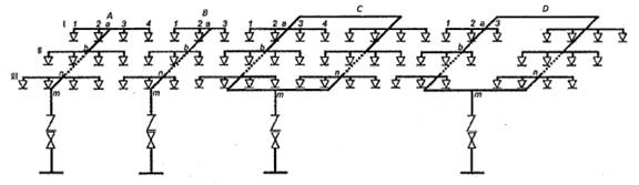
A - Mạng đối xứng; B - Mạng bất đối xứng; C - Mạng vòng đối xứng; D - Mạng vòng bất đối xứng; I, II, III- các hàng của đường ống phân phối; a, b... n, m - các điểm nút
B.2.2 Lưu lượng nước chữa cháy (dung dịch chất tạo bọt) qua đầu phun chủ đạo nằm trong khu vực tính toán được xác định theo công thức:

trong đó:
q1 - lưu lượng chất chữa cháy qua đầu phun, l/s;
K - hệ số hiệu suất của đầu phun, được lấy từ tài liệu kỹ thuật, l/(s.MPa0,5);
P - áp suất tại đầu phun, MPa.
B.2.3 Lưu lượng của đầu phun số 1 là giá trị lưu lượng tính toán Q1-2 trong đoạn đường ống L1-2 giữa các đầu phun thứ nhất và thứ hai (hình 1, phần A).
B.2.4 Đường kính của đường ống trong đoạn L1-2 được xác định theo công thức:
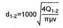
Trong đó:
d1-2 - đường kính ống giữa các đầu phun số 1 và số 2, mm;
Q1-2 - lưu lượng chất chữa cháy, l/s;
μ - hệ số dòng chảy (lấy bằng 1 đối với dòng chảy tầng);
v - vận tốc nước, m / s (không được vượt quá 10 m/s).
B.2.5 Tổn thất P1-2 ở đoạn L1-2 được xác định theo công thức:

Trong đó:
KT - đặc tính thủy lực của đường ống, l6/s2;
A - sức cản đơn vị của đường ống, tùy thuộc vào đường kính và độ nhám của ống s2/l6
B.2.6 Sức cản đơn vị và đặc tính thủy lực của đường ống cho các loại đường ống (làm bằng vật liệu carbonate) có đường kính khác nhau được nêu trong Bảng B.1 và B.2.
Bảng B.1- Sức cản đơn vị ở các mức độ nhám khác nhau của ống
|
Đường kính |
Sức cản đơn vị A, s2/l6 |
|||
|
Đường kính danh định DN |
Tính toán, mm |
Độ nhám lớn nhất |
Độ nhám vừa |
Độ nhám nhỏ nhất |
|
20 |
20,25 |
1,643 |
1,15 |
0,98 |
|
25 |
26 |
0,4367 |
0,306 |
0,261 |
|
32 |
34,75 |
0,09386 |
0,0656 |
0,059 |
|
40 |
40 |
0,04453 |
0,0312 |
0,0277 |
|
50 |
52 |
0,01108 |
0,0078 |
0,00698 |
|
70 |
67 |
0,002893 |
0,00202 |
0,00187 |
|
80 |
79,5 |
0,001168 |
0,00082 |
0,000755 |
|
100 |
105 |
0,0002674 |
0,000187 |
- |
|
125 |
130 |
0,00008623 |
0,0000605 |
- |
|
150 |
155 |
0,00003395 |
0,0000238 |
- |
Bảng B.2- Đặc tính thủy lực của đường ống
|
Loại ống |
Đường kính danh định DN |
Đường kính ngoài, mm |
Độ dày, mm |
Đặc tính thủy lực của đường ống KT, x 10-6 l6/s2 |
|
Ống thép hàn điện |
15 |
18 |
2,0 |
0,0755 |
|
20 |
25 |
2,0 |
0,75 |
|
|
25 |
32 |
2,2 |
3,44 |
|
|
32 |
40 |
2,2 |
13,97 |
|
|
40 |
45 |
2,2 |
28,7 |
|
|
50 |
57 |
2,5 |
110 |
|
|
65 |
76 |
2,8 |
572 |
|
|
80 |
89 |
2,8 |
1429 |
|
|
100 |
108 |
2,8 |
4322 |
|
|
100 |
108 |
3,0 |
4231 |
|
|
100 |
114 |
2,8 |
5872 |
|
|
100 |
114* |
3,0* |
5757 |
|
|
125 |
133 |
3,2 |
13530 |
|
|
125 |
133* |
3,5* |
13190 |
|
|
125 |
140 |
3,2 |
18070 |
|
|
150 |
152 |
3,2 |
28690 |
|
|
150 |
159 |
3,2 |
36920 |
|
|
150 |
159* |
4,0* |
34880 |
|
|
200 |
219* |
4,0* |
209900 |
|
|
250 |
273* |
4,0* |
711300 |
|
|
300 |
325* |
4,0* |
1856000 |
|
|
350 |
377* |
5,0* |
4062000 |
|
|
Đường ống thép dẫn khí và nước |
15 |
21,3 |
2,5 |
0,18 |
|
20 |
26,8 |
2,5 |
0,926 |
|
|
25 |
33,5 |
2,8 |
3,65 |
|
|
32 |
42,3 |
2,8 |
16,5 |
|
|
40 |
48 |
3,0 |
34,5 |
|
|
50 |
60 |
3,0 |
135 |
|
|
65 |
75,5 |
3,2 |
517 |
|
|
80 |
88,5 |
3,5 |
1262 |
|
|
90 |
101 |
3,5 |
2725 |
|
|
100 |
114 |
4,0 |
5205 |
|
|
125 |
140 |
4,0 |
16940 |
|
|
150 |
165 |
4,0 |
43000 |
CHÚ THÍCH: Các ống có thông số được đánh dấu bằng "*" được sử dụng trong các mạng đường cấp nước bên ngoài.
B.2.7 Sức cản đơn vị của ống nhựa được lấy theo thông số của nhà sản xuất, cần lưu ý, không giống như đường ống thép, đường kính của ống nhựa được biểu thị bằng đường kính ngoài.
B.2.8 Áp suất tại đầu phun 2:
P2 = P1 + P1-2
B.2.9 Lưu lượng tại đầu phun 2:

B.2.10 Tính toán mạng đường ống cụt đối xứng
B.2.10.1 Đối với sơ đồ đối xứng (Hình B.1, Phần A), lưu lượng tính toán trong đoạn ống nối giữa đầu phun 2 và điểm a là:
Q2-a = q1 + q2
B.2.10.2 Đường kính của đường ống 2-a lấy theo thiết kế hoặc được xác định theo công thức:
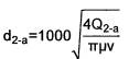
B.2.10.3 Tổn thất tại đoạn ống 2-a:

B.2.10.4 Áp suất tại điểm a sẽ là:
Pa = P2 + P2-a
B.2.10.5 Đối với nhánh bên trái của hàng I (Hình B.1, Phần A), cần phải đảm bảo lưu lượng Q2-a theo áp suất Pa. Nhánh bên phải đối xứng với nhánh bên trái, do đó lưu lượng của nhánh này cũng sẽ bằng Q2-a, và do đó, áp suất tại điểm a sẽ bằng Pa
B.2.10.6 Kết quả là, đối với hàng I, có áp suất bằng Pa, và lưu lượng:
Ql = 2Q2-a
B.2.10.7 Đường kính của đoạn ống a-b lấy theo thiết kế hoặc được xác định theo công thức:
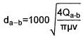
B.2.10.8 Đặc tính thủy lực của các hàng có cấu trúc giống nhau, được xác định bởi đặc tính tổng quát của phần đường ống tính toán.
B.2.10.9 Đặc tính tổng quát của hàng I được xác định từ công thức:
Bpl= Q2l/Pa
B.2.10.10 Tổn thất tại đoạn a -b cho các sơ đồ đối xứng và không đối xứng (Hình B.1, phần A và B) được xác định từ công thức:

B.2.10.11 Áp suất của điểm b là
Pb = Pa+Pa-b
B.2.10.12 Lưu lượng nước từ hàng II được xác định bởi công thức:

B.2.10.13 Việc tính toán tất cả các hàng tiếp theo để có được lưu lượng nước tính toán (thực tế) và áp suất tương ứng được thực hiện tương tự như tính toán của hàng II.
B.2.11 Tính toán mạng cụt không đối xứng
B.2.11.1 Phần bên phải của phần B (Hình B.1) không đối xứng với bên trái, do đó, nhánh bên trái được tính riêng, xác định cho nó Pa và Q3-a
B.2.11.2 Nếu xem xét phía bên phải 3-a (một đầu phun) tách biệt với bên trái 1-a (hai đầu phun), thì áp suất ở phía bên phải P’a phải nhỏ hơn áp suất Pa ở bên trái.
B.2.11.3 Vì không thể có hai áp suất khác nhau tại một điểm, nên lấy giá trị áp suất lớn hơn Pa và xác định lưu lượng được điều chỉnh (đã điều chỉnh) cho nhánh phải Q3-a:
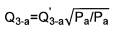
B.2.11.4 Tổng lưu lượng từ hàng I:
Ql = Q2-a+Q3-a
B.2.12 Tính toán mạng vòng đối xứng và bất đối xứng
Mạng vòng đối xứng và không đối xứng (Hình B.1, phần C và D) được tính toán tương tự như mạng lưới cụt, nhưng ở mức 50% lưu lượng nước tính toán cho mỗi nửa vòng.
B.3 Tính toán thủy lực hệ thống chữa cháy tự động
B.3.1 Tính toán hệ thống chữa cháy tự động Sprinkler với điều kiện:
QH ≤ QC
Trong đó:
QH - Lưu lượng cần thiết của hệ thống theo bảng 1, 2, 3 của tiêu chuẩn này;
QC - Lưu lượng thực tế của hệ thống.
B.3.2 Số lượng đầu phun đảm bảo lưu lượng cần thiết của hệ thống với cường độ phun không nhỏ hơn tiêu chuẩn (có tính đến đặc điểm của khu vực bảo vệ) phải bảo đảm:
n ≥ S/Ω
Trong đó:
n - số lượng đầu phun tối thiểu, đảm bảo lưu lượng cần thiết với cường độ phun không nhỏ hơn tiêu chuẩn;
S- diện tích phun tối thiểu theo bảng 1 của các tiêu chuẩn này;
Ω - khu vực tính toán theo thiết kế được bảo vệ bởi một đầu phun:
Ω = L2
L là khoảng cách giữa các đầu phun.
B.3.3 Đường kính của các phần riêng biệt của đường ống phân phối có thể được chọn theo số lượng đầu phun được lắp đặt trên nó. Bảng B.3 cho thấy mối quan hệ giữa đường kính của các đường ống phân phối, áp suất và số lượng đầu phun nước được lắp đặt.
Bảng B.3 - Mối quan hệ gần đúng giữa các đường kính được sử dụng phổ biến nhất của đường ống phân phối, áp suất và số lượng đầu phun Sprinkler hoặc Drencher được lắp đặt
|
Đường kính của ống, DN |
20 |
25 |
32 |
40 |
50 |
70 |
80 |
100 |
125 |
150 |
|
Số lượng đầu phun nước có áp suất 0,5 MPa trở lên |
1 |
3 |
5 |
9 |
18 |
28 |
46 |
80 |
150 |
Trên 150 |
|
Số lượng đầu phun có áp suất đến 0,5 MPa |
- |
2 |
3 |
5 |
10 |
20 |
36 |
75 |
140 |
Trên 140 |
B.3.4 Do áp suất của mỗi đầu phun là khác nhau (đầu phun chủ đạo có áp suất thấp nhất), nên cần xem xét lưu lượng của mỗi đầu phun trong tổng số n đầu phun.
B.3.5 Tổng lưu lượng cần thiết của hệ thống chữa cháy tự động Sprinkler được tính theo số lượng đầu phun cần thiết trên khu vực được bảo vệ.
B.3.6 Tổng lưu lượng cần thiết của hệ thống chữa cháy tự động Drencher được tính bằng tổng lưu lượng của các đầu phun trong khu vực được bảo vệ:

Trong đó:
Qd - Lưu lượng tính toán của hệ thống, l/s;
qn -Lưu lượng tại đầu phun thứ n, l/s;
n - số lượng đầu phun nằm trong khu vực bảo vệ
B.3.7 Lưu lượng QCCTĐ của hệ thống chữa cháy tự động Sprinkler kết hợp màn nước:
QCCTĐ = Qs + Qd
Trong đó:
Qs - Lưu lượng của hệ thống Sprinkler;
Qd - Lưu lượng của màn nước
B.3.8 Đối với đường ống nước chữa cháy kết hợp (hệ thống họng nước chữa cháy trong nhà và hệ thống chữa cháy tự động), được phép lắp đặt chung cụm bơm, với điều kiện cụm bơm này có lưu lượng bằng tổng lưu lượng của từng hệ thống:
Q = QCCTĐ + QTN
Trong đó, QCCTĐ, QTN - lưu lượng tương ứng của hệ thống chữa cháy tự động và hệ thống họng nước chữa cháy trong nhà.
B.3.9 Áp suất cần thiết của máy bơm chữa cháy bao gồm các thành phần sau:

Trong đó:
PB - áp suất cần thiết của bơm chữa cháy, MPa;
PDĐ1 - tổn thất dọc đường theo phương ngang của đường ống, MPa;
PDĐ2 - tổn thất dọc đường theo phương đứng của đường ống, MPa
PCB1 - tổn thất cục bộ, MPa;
PCB2 - tổn thất cục bộ của thiết bị điều khiển (van bảo động, van cổng), MPa;
PĐP - áp lực tại đầu phun, MPa;
Z - Áp suất do chênh lệch độ cao giữa đầu phun với trục của bơm chữa cháy), MPa; Z = H/100
PH - áp suất ở đầu vào của máy bơm chữa cháy, MPa
B.3.10 Từ điểm n (hình B.1, phần A và B) hoặc từ điểm m (hình B.1, phần C và D) đến máy bơm chữa cháy (hoặc thiết bị cấp nước khác) tổn thất áp lực được tính toán theo chiều dài đường ống có tính đến tổn thất cục bộ, bao gồm các thiết bị điều khiển (van tín hiệu, van).
B.3.11 Tổn thất áp lực trong đường ống chính được xác định bằng cách tính tổng tổn thất áp lực từng đoạn ống bằng các công thức:

Trong đó:
∆Pi - tổn thất áp lực đoạn Li, MPa
Q- lưu lượng chất chữa cháy, l/s
KT - đặc tính thủy lực của đường ống đoạn Li, l6/s2
A - sức cản đơn vị của đường ống tại đoạn Li, tùy thuộc vào đường kính và độ nhám của ống, s2/l6
B.3.12 Tổn thất cục bộ tại các thiết bị điều khiển của hệ thống PCB2, m, được xác định theo công thức
- Đối với Sprinkler:

- Đối với Drencher:

Trong đó:
 tương ứng là các hệ số tổn thất của bộ điều khiển, trong van báo động và van khóa (được lấy từ tài liệu kỹ thuật);
γ - khối lượng riêng của nước, kg/m3;
Q - Lưu lượng nước tính toán qua bộ điều khiển, m3/h.
B.3.13 Trong tính toán gần đúng, tổn thất cục bộ (bao gồm cả tổn thất trong bộ điều khiển) được giả định bằng 20% tổn thất dọc đường mạng lưới đường ống; không cần tính trong trường hợp hệ thống chữa cháy tự động bằng bọt khi nồng độ của dung dịch chất tạo bọt đến 10%.
B.3.14 Việc tính toán được thực hiện sao cho áp suất tại bộ điều khiển không vượt quá 1 MPa, trừ khi có quy định khác theo thông số kỹ thuật.
B.3.15 Đối với nhóm đối tượng bảo vệ (Phụ lục A), phải tính thời gian chữa cháy theo Bảng 1.
B.3.16 Thời gian làm việc của hệ thống họng nước chữa cháy trong nhà kết hợp với hệ thống chữa cháy tự động phải lấy bằng thời gian của hệ thống chữa cháy tự động.
Phương pháp tính toán các thông số của hệ thống chữa cháy bằng bọt bội số nở cao
C.1 Phải xác định thể tích tính toán V, m3 của không gian được bảo vệ hoặc thể tích chữa cháy cục bộ. Thể tích tính toán của gian phòng được xác định bởi diện tích sàn và chiều cao của gian phòng khi chứa đầy bọt, ngoại trừ thể tích của các cấu kiện chống cháy (không thấm nước) của nhà (cột, dầm, móng, v.v.).
C.2 Với chủng loại và nhãn hiệu của thiết bị tạo bọt bột số nở cao đã lựa chọn, hiệu suất của chúng được xác định dựa trên đặc tính dung dịch chất tạo bọt q, l/min.
C.3 Tính toán số lượng thiết bị tạo bọt bội số nở cao theo công thức:
|
|
(D.1) |

Trong đó:
K - bội số nở của bọt (lấy theo thông số kỹ thuật của thiết bị tạo bọt);
τ - thời gian tối đa để lấp đầy không gian được bảo vệ bằng bọt, min;
a - hệ số phá hủy bọt.
Giá trị của hệ số a được tính theo công thức
|
a = a1 a2 a3 |
(D.2) |
Trong đó:
a1 - hệ số độ co của bọt, được lấy bằng 1,2 với chiều cao phòng lên tới 4 m và 1,5 với chiều cao phòng lên tới 10 m, với chiều cao phòng trên 10 m được xác định bằng thử nghiệm.
a2 - hệ số tính đến rò rỉ bọt, trong trường hợp không có lỗ mở được lấy bằng 1,2, khi có các lỗ mở được xác định bằng thực nghiệm;
a3 - hệ số đến ảnh hưởng của khói, khí cháy đến sự phá hủy bọt, với các sản phẩm cháy của chất lỏng hydrocarbon, giá trị hệ số được lấy bằng 1,5, đối với các loại chất cháy khác được xác định bằng thực nghiệm.
Thời gian tối đa để lấp đầy thể tích của không gian được bảo vệ bằng bọt không quá 10 min.
C.4 Xác định lưu lượng dung dịch chất tạo bọt cần thiết của hệ thống, m3/s

C.5 Nồng độ thể tích của dung dịch chất tạo bọt lấy theo tài liệu kỹ thuật c,%.
C.6 Lượng chất tạo bọt tính toán được xác định, m3:


[2] QCVN 06:2021: An toàn cháy cho nhà và công trình.
[3] TCVN 5738:2021: Phòng cháy chữa cháy - Hệ thống báo cháy tự động - Yêu cầu kỹ thuật.
[4] TCVN 6305-2:2007 (ISO 6182-2:2005): Phòng cháy chữa cháy - Hệ thống Sprinkler tự động - Phần 2: Yêu cầu và phương pháp thử đối với van báo động kiểu ướt, bình làm trễ và chuông nước.
[5] TCVN 6305-3:2007 (ISO 6182-3:2005): Phòng cháy chữa cháy - Hệ thống Sprinkler tự động - Phần 3: Yêu cầu và phương pháp thử đối với van đường ống khô.
[6] TCVN 6305-4:1997 (ISO 6182-4:1993): Phòng cháy chữa cháy - Hệ thống Sprinkler tự động - Phần 4: Yêu cầu và phương pháp thử đối với cơ cấu mở nhanh.
[7] TCVN 6305-5:2009 (ISO 6182-5:2006): Phòng cháy chữa cháy - Hệ thống Sprinkler tự động - Phần 5: Yêu cầu và phương pháp thử đối với van tràn.
[8] TCVN 6305-10:2013 (ISO 6182-10:2006): Phòng cháy chữa cháy - Hệ thống Sprinkler tự động - Phần 5: Yêu cầu và phương pháp thử đối với Sprinkler trong nhà.
MỤC LỤC
Lời nói đầu
1 Phạm vi áp dụng
2 Tài liệu tham khảo
3 Các thuật ngữ và định nghĩa
4 Các quy định chung
5 Các hệ thống chữa cháy tự động Sprinkler, Drencher bằng nước và bằng bọt
6 Hệ thống chữa cháy tự động bằng bọt bội số nở cao
7 Thiết bị điều khiển hệ thống chữa cháy tự động
8 Cấp điện cho hệ thống chữa cháy tự động
9 Yêu cầu an toàn và bảo vệ nối đất
Phụ lục A Phân loại cơ sở theo nhóm nguy cơ phát sinh cháy, phụ thuộc vào công năng và tải trọng cháy
Phụ lục B Phương pháp tính toán các thông số của hệ thống chữa cháy theo bề mặt với chất chữa cháy nước hoặc bọt bội số nở thấp
Phụ lục C Phương pháp tính toán các thông số của hệ thống chữa cháy bằng bọt bội số nở cao
NATIONAL STANDARDS
TCVN 7336:2021
FIRE PROTECTION - WATER, FOAM AUTOMATIC FIRE-EXTINGUISHING SYSTEMS - DESIGN AND INSTALLATION REQUIREMENTS
PREFACE
TCVN 7336:2021 replaces the TCVN 7336:2003
TCVN 7336:2021 is developed on the basis of the Code of practices SP 5.13130.2009 of the Russian Federation
TCVN 7336:2021 is composed by the Central Department of Fire safety, Firefighting, and Rescue, proposed by Ministry of Public Security, appraised by the Directorate for Standards, Metrology, and Quality, and publicized by Ministry of Science and Technology.
FIRE PROTECTION - WATER, FOAM AUTOMATIC FIRE-EXTINGUISHING SYSTEMS - DESIGN AND INSTALLATION REQUIREMENTS
1 Scope of regulation
1.1 These standards prescribe requirements for designing and installing water, foam automatic fire-extinguishing systems in buildings and structures.
1.2 These standards shall not be adopted for designing water, foam automatic fire-extinguishing systems in:
- Buildings and structures designed in accordance with special regulations;
- Technology equipment located outdoors;
- Warehouses equipped with mobile construction brackets.
1.3 These standards shall not be adopted for designing water, foam fire-extinguishing systems for extinguishing fires of metals or chemically active substances and materials, including those:
- Reacting with fire extinguishing agents causing explosion (organoaluminum, alkali materials, etc.);
- Decomposing in case of contact with fire extinguishing agents, causing emission of combustible gases (lead azide, aluminum hydrates, zinc, magnesium);
- Reacting with fire extinguishing agents causing powerful exothermic effect (sulphuric acid, titanium chloride, etc.);
- Igniting by themselves upon contact with water (sodium hydrosulphite, etc.).
2 Reference documents
Reference documents below are necessary for adoption of these Standards. Regarding reference documents stated with year of publication, apply the stated version. Regarding reference documents not stated with year of publication, apply the latest version including amendments thereto (if any).
TCVN 6305-1: Fire protection - Automatic Sprinkler system - Part 1: Requirements and test methods for sprinklers
3 Terms and interpretation
These Standards apply following terms and interpretation:
3.1
Automatic extinguishing
Means automatic activation of fire-extinguishing equipment without human participation.
Automatic extinguishing system
Means a fire extinguishing system which is automatically activated when fire factors exceed the threshold in the protected zone (hereinafter referred to as “AES”).
Automatic water feeder
Means a water feeder that automatically maintain in pipeline the pressure needed for activation of control units.
Accelerator
Means a device assuring acceleration of air discharge in pipeline by compressed air in standby state in case of sprinkler activation.
Branch of distribution pipeline
Means a pipeline branching from the feeding pipeline
Water-filled pipeline
Means a pipeline whose pressure is maintained by water.
NOTE: The design aims to allow operation in temperature above 0 degree Celsius.
Air-filled pipeline
Means a pipeline whose pressure is maintained by compressed air.
Water feeder
Means a device assuring operation of AES with design water flow and pressure of water and (or) water solution set forth in the technical documentation throughout the established time.
Auxiliary water feeder
Means a water feeder automatically maintaining pressure in pipelines needed for activation of control units, as well as maintaining design flow and pressure of water and (or) water solutions until the moment of activation of the operating mode of the main water feeder.
Standby mode of automatic extinguishing system
Means the state of readiness of the AES.
Dictating irrigator
Means an irrigator which is located at the most hydraulically disadvantageous position, usually at the highest and/or furthest away from control units.
Remote activation of the system
Means a manual activation by activating equipment situated in or close to a protected area or in a control station.
Metering unit
Means a device designed to mix foaming agent with water in a proportion.
Irrigator
Means a device designed to spray water and/or fire extinguishing agent to extinguish or slow down the fire.
Sprinkler irrigator
Means an irrigator designed to activate at a predetermined temperature.
Drencher irrigator
Means an irrigator with open outlet.
Minimum irrigation area
Means a standard (for sprinkler AES) or rated (for drencher AES) area, where standard irrigation intensity and design flow rate of fire extinguishing agent are assured.
Response time of extinguishing system
Means the time starting from the moment where fire factors reach the working threshold of a fire detector or an irrigator or a fire alarm to the moment where fire extinguishing agent is sprayed in the protected area.
NOTE: For fire extinguishing system that requires a delay prior to the release of fire extinguishing agent to allow human evacuation from protected area and equipment operation, this delay is included in the response time of the system.
Intensity of extinguishing agent supply
Means the amount of fire extinguishing agent sprayed in a fire per a unit of area (volume) per a unit of time.
Retard chamber
Means a device fitted on the alarm valve to minimize the possibility of a false alarm when the alarm valve is opened as a result of the sudden change in pressure of water supply source.
Local actuation of a system
Means actuation of the system done by equipment installed at the fire pump station.
Fire pump station
Means a combination of equipment including fire pumps, pressure compensated pumps, and other accessories connected to each other to create a water supply system for extinguishing fire.
Shut-off device
Means a device for feeding, regulating, and shutting off the flow of fire extinguishing agent.
Operating mode of an automatic extinguishing system
Means when the AES performs fire extinguishing function after being activated.
Distribution pipeline
Means a pipeline where irrigators are fitted.
Reserve of extinguishing agent
Means the reserved amount of extinguishing agent necessary and ready for immediate use in case of fire or when extinguishing agent in the main supply cannot be accessed.
Section of extinguishing system
Means a part of the fire extinguishing system created by the feeding pipeline, branch of distribution pipeline, control unit, and technical equipment which supplies the protected area with fire extinguishing agent.
Pressure switch
Means a device converting pressure signal to logic command.
Flow switch
Means a device converting flow rate of a pipeline to logic command.
Alarm valve
Means a valve which is usually closed and designed to send alarm signal and allow extinguishing agent to pass once irrigators are activated.
3.31 Specific flow rate of water curtain
Means flow rate of water per one meter in length and per one unit of time.
Control unit
Means a combination of technical means of water and foam AES (pipelines, valves, shut-off and warning devices, accelerators, retarders, devices reducing probability of false activations, measuring instruments and other devices) that are located between the distribution and the feeding pipelines for monitoring of the performance of these devices in the course of operation, as well as for delivery of fire extinguishing agent, signaling for operation of elements of automatic fire-fighting systems (fire pumps, alarm system, ventilation, process equipment, and others).
Air compensator
Means a device for compensating for the air leaked along the feeding pipeline, and air-filled distribution pipeline to minimize the possibility of false alarm of the alarm valve.
4 General provisions
4.1 Water, foam AES must be able to perform fire warning task in addition to fire extinguishing task.
4.2 Type of AES, fire extinguishing method, and type of fire extinguishing agent must take into account fire risk and physical, chemical properties of fire fuels and characteristics of protected entities
4.3 When installing AES in buildings and buildings whose rooms are separate and mandated by the law to be fitted with only fire alarm system, may install AES instead. If AES is installed in this case, intensity of extinguishing agent supply must conform to standards regardless of flow rate and fire extinguishing duration.
4.4 AES must be actuated by equipment control signals in the protected area according to technological demands or these standards before releasing fire extinguishing agent.
5 Water, foam Sprinkler and Drencher AES
5.1 General provisions
5.1.1 Water, foam AES must be able to extinguish the fire or prevent fire spread.
5.1.2 Water, foam AES shall be divided into Sprinkler system, Drencher system, and Sprinkler-Drencher system.
5.1.3 Parameters of water, foam AES under Article 5.1.2 (minimum supply intensity, minimum flow rate, minimum calculated area, minimum supply duration, and maximum distance between irrigators) are elaborated under Schedules 1, 2, and 3 and fire risk groups are specified under Appendix A.
Schedule 1. Parameters of water, foam AES
|
Fire risk group |
Minimum supply intensity (l/s.m2) |
Minimum flow rate(1) (l/s) |
Minimum calculated area(1) (m2) |
Minimum supply duration |
Maximum distance between irrigators(1) (m) |
||
|
Water |
Foaming solution |
Water |
Foaming solution |
||||
|
1 |
0,08 |
- |
10 |
- |
60 |
30 |
4 |
|
2 |
0,12 |
0,08 |
30 |
20 |
120 |
60 |
4 |
|
3 |
0,24 |
0,12 |
60 |
30 |
120 |
60 |
4 |
|
4.1 |
0,3 |
0,15 |
110 |
55 |
180 |
60 |
4 |
|
4.2 |
- |
0,17 |
- |
65 |
180 |
60 |
3 |
|
5 |
See Schedule 2 |
90 |
60 |
3 |
|||
|
6 |
See Schedule 2 |
90 |
60 |
3 |
|||
|
7 |
See Schedule 2 |
90 |
(10-25)(2) |
3 |
|||
|
NOTE 1: (1) Applies to Sprinkler AES and Sprinkler-Drencher AES; (2) Supply duration of low and medium expansion: 25 min - for rooms of fire risk group 7; 15 min - for rooms of fire risk categories A, B, and C1; 10 min - for rooms of fire risk categories C2 and C3. NOTE 2: Fire risk groups are elaborated under Appendix A. NOTE 3: For fire extinguishing systems utilizing water mixed with additives (adhering to technical parameters and requirements of manufacturers) in order to increase permeability on the basis of mixing with foaming agent, supply intensity and flow rate can be reduced by 1.5 times compared to those when utilizing water only. NOTE 4: For Sprinkler system, the supply intensity and flow rate of water or foaming solution shall apply to rooms lower than 10 m in height and rooms with skylight whose area does not exceed 10% of roof area. If skylight of a room exceeds 10% of the roof area, the height of the room shall extend to the canopies. Parameters applying to rooms whose height ranges from 10 to 20 m shall conform to Schedules 2 and 3. NOTE 5: If actually protected area (Stt) is lower than the calculated minimum area (S) under Schedule 1, actual flow rate can be reduced following K = Stt / S NOTE 6: In order to calculate flow rate of Drencher system, identify number of irrigators in protected area and calculate in accordance with Appendix B (with irrigation intensity under Schedules 1, 2, and 3 corresponding to fire risk groups under Appendix A). NOTE 7: This Schedule specifies irrigation intensity of regular foaming solution. NOTE 8: For Drencher extinguishing system, allow distance between irrigators to be greater than values under Schedule 1. If that is the case, irrigation intensity across protected area must be guaranteed and not contradicting technical documents applied to these irrigators. NOTE 9: Distance between irrigators below pitched roofs or ceilings shall be determined by their projections on a horizontal plane. |
|||||||
Schedule 2. Irrigation intensity and flow rate of water, foam AES of rooms in warehouses under fire risk groups 5, 6, and 7
|
Stacking height of materials and goods (m) |
Fire risk groups |
|||||
|
5 |
6 |
7 |
||||
|
With water |
With foaming solution |
With water |
With foaming solution |
With water |
With foaming solution |
|
|
Minimum irrigation intensity (according to Schedule 1) (l/s.m2) |
||||||
|
Up to 1 |
0,08 |
0,04 |
0,16 |
0,08 |
- |
0,1 |
|
Exceeding 1 to 2 |
0,16 |
0,08 |
0,32 |
0,2 |
- |
0,2 |
|
Exceeding 2 to 3 |
0,24 |
0,12 |
0,40 |
0,24 |
- |
0,3 |
|
Exceeding 3 to 4 |
0,32 |
0,16 |
0,40 |
0,32 |
- |
0,4 |
|
Exceeding 4 to 5,5 |
0,4 |
0,32 |
0,50 |
0,40 |
- |
0,4 |
|
Minimum flow rate (l/s) |
||||||
|
Up to 1 |
15 |
7,5 |
30 |
15 |
- |
18 |
|
Exceeding 1 to 2 |
30 |
15 |
60 |
36 |
- |
36 |
|
Exceeding 2 to 3 |
45 |
22,5 |
75 |
45 |
- |
54 |
|
Exceeding 3 to 4 |
60 |
30 |
75 |
60 |
- |
75 |
|
Exceeding 4 to 5,5 |
75 |
37,5 |
90 |
75 |
- |
75 |
|
NOTE 1: Fire risk group is elaborated under Appendix A. NOTE: In fire risk group 6, when extinguishing fire of rubber, rubber and plastic materials, use water mixed with additives to improve permeability or low expansion foam. NOTE 3: For warehouses where materials and goods are stacked up to 5,5 m and the room is taller than 10m, flow rate and intensity of water and foaming solution in fire risk groups 5, 6, and 7 must be increased by 10% for every extra 2 m in room’s height. NOTE 4: This Schedule specifies irrigation intensity of regular foaming solution. NOTE 5: Allow the design of AES for the case where materials and goods are stacked higher than 5,5 m after conducting experiments verifying primary design parameters; this applies to specific technical conditions of similar entities approved by competent authorities. |
||||||
Schedule 3. Parameters of water, foam AES of rooms whose height ranges from 10 m to 20 m
|
Height of protected area (m) |
Fire risk groups |
|||||||
|
Group 1 |
Group 2 |
Group 3 |
Group 4.1 |
Group 4.2 |
||||
|
With water |
With water |
With foaming solution |
With water |
With foaming solution |
With water |
With foaming solution |
With foaming solution |
|
|
Minimum supply intensity (l/s.m2) |
||||||||
|
From 10 to 12 |
0,09 |
0,13 |
0,09 |
0,26 |
0,13 |
0,33 |
0,17 |
0,20 |
|
Exceeding 12 to 14 |
0,1 |
0,14 |
0,1 |
0,29 |
0,14 |
0,36 |
0,18 |
0,22 |
|
Exceeding 14 to 16 |
0,11 |
0,16 |
0,11 |
0,31 |
0,16 |
0,39 |
0,2 |
0,25 |
|
Exceeding 16 to 18 |
0,12 |
0,17 |
0,12 |
0,34 |
0,17 |
0,42 |
0,21 |
0,27 |
|
Exceeding 18 to 20 |
0,13 |
0,18 |
0,13 |
0,36 |
0,18 |
0,45 |
0,23 |
0,30 |
|
Minimum flow rate (l/s) |
||||||||
|
From 10 to 12 |
12 |
35 |
25 |
70 |
35 |
130 |
65 |
95 |
|
Exceeding 12 to 14 |
14 |
40 |
30 |
85 |
45 |
155 |
80 |
115 |
|
Exceeding 14 to 16 |
17 |
50 |
35 |
95 |
50 |
180 |
90 |
140 |
|
Exceeding 16 to 18 |
20 |
57 |
40 |
115 |
60 |
215 |
105 |
165 |
|
Exceeding 18 to 20 |
24 |
65 |
50 |
130 |
65 |
240 |
120 |
195 |
|
Minimum calculated area (m2) |
||||||||
|
From 10 to 12 |
66 |
132 |
132 |
198 |
238 |
|||
|
Exceeding 12 to 14 |
72 |
144 |
144 |
216 |
259 |
|||
|
Exceeding 14 to 16 |
78 |
156 |
156 |
230 |
276 |
|||
|
Exceeding 16 to 18 |
84 |
168 |
168 |
252 |
303 |
|||
|
Exceeding 18 to 20 |
90 |
180 |
180 |
270 |
325 |
|||
|
NOTE 1: Fire risk category is elaborated under Appendix A. NOTE 2: Flow rate and intensity shall apply to water and foam irrigators with regular structure NOTE 3: This Schedule specifies irrigation intensity of regular foaming solution. NOTE 4: In case actual area (Stt) of area protected by water, foam AES is less than the minimum calculated area (S) of the Sprinkler, Sprinkler-Drencher AES under Schedule 3, actual flow rate can be reduced following K = Stt/S. |
||||||||
5.1.4 Maximum pressure of water and foam irrigators must not exceed 1 MPa unless otherwise regulated for specific protected entities or similar entities by technical documents.
5.1.5 Hydraulic calculation of water and foam Sprinkler and Drencher and Sprinkler-Drencher AES is elaborated under Appendix B.
5.1.6 When fire rooms where electrical equipment is not insulated is extinguished using water and foam, cut power source prior to spraying extinguishing agent at the fire.
Allow actuation of AES to extinguish fire of uninsulated electrical equipment when adopting specific solutions for similar entities under technical conditions approved by competent authorities.
5.1.7 AES other than Sprinkler must be fitted with manual actuation mechanisms that allow:
Remote actuation - from equipment installed at entrance of protected area and control station if necessary;
Local actuation - from equipment installed at control unit or fire pump station.
5.1.8 Equipment that facilitates manual actuation must be protected from the risk of unintentional actuation and physical damage and must not be located where fire fuels are situated.
5.1.9 All Sprinkler irrigators in the same room must have the same actuation temperature and technical parameters. Water curtain Drencher irrigators may have parameters different from those of Sprinkler irrigators fitted in the same room as long as all technical parameters of Drencher irrigators fitted in the same room must be identical.
5.1.10 Irrigators must be fitted in accordance with Schedule 1 and accounting for technical parameters of irrigators (installation position, actuation temperature, irrigation intensity, characteristic curves, etc.) and requirements under technical documents of manufacturers.
5.1.11 The gap between irrigators and the highest point of fire fuels, technology equipment, or building structures must account for working pressure threshold and shape of the spray.
5.1.12 Prepare spare Sprinkler and Drencher irrigators in AES as follows:
- 3 Sprinkler spare irrigators for AES with up to 100 Sprinkler irrigators, 1 spare Drencher irrigator for AES with up to 100 Drencher irrigators;
- 10 spare Sprinkler irrigators for AES with up to 1000 Sprinkler irrigators, 2 spare Drencher irrigators for AES with up to 1000 Drencher irrigators;
- 15 spare Sprinkler irrigators for AES with more than 1000 Sprinkler irrigators, 3 spare Drencher irrigators for AES with more than 1000 Drencher irrigators;
For experimentation purposes, number of spare Sprinkler irrigators must not be lower than twice the number of irrigators per minimum calculated area under Schedule 1 for every area with different fire risk group of the structure.
5.1.13 May fit pendent Sprinkler irrigators and concealed Sprinkler irrigators in rooms with fire risk group 1 (Appendix A) and suspended ceiling.
5.1.14 May fit shut-off valves ahead of flow switch if flow switch is used.
5.1.15 Shut-off valves fitted along pipelines supplying fire pumps, feeding pipelines, and distribution pipelines must allow visual inspection of their closed-opened status.
5.1.16 Situate positions within protected areas that allow drainage or treatment of overflown water and/or fire extinguishing agent during experimentation or operation of fire extinguishing system.
5.2 Sprinkler system
5.2.1 The selection of whether to install water, wet foam or dry foam extinguishing system must be made based on ambient temperature of protected area.
5.2.2 Irrigators are designed for rooms no taller than 20 m.
5.2.3 Each irrigation section of the system must not employ more than 800 irrigators. The number of irrigators per section of protected area may be increased to 1200 irrigators if flow switch is used for each section of protected area or if irrigators allow visual inspection of operation status.
5.2.4 Regarding irrigators fitted on air-filled pipelines, the response time of the system must not exceed 180 s.
5.2.5 If response time of the system, in case irrigators are fitted on air-filled pipelines, is greater than 180 s, accelerators or exhauster must be used.
5.2.6 Maximum working pressure of compressed air in distribution and feeding pipelines of dry Sprinkler and Sprinkler-Drencher AES must be selected so as to ensure that the response time of the system does not exceed 180 s.
5.2.7 It must not take more than 1 hour to fill air-filled pipelines of Sprinkler system or Sprinkler-Drencher system with air until working pressure is reached.
5.2.8 Air compensators must be calculated in order to compensate for air leak that occurs from pipelines of air-filled Sprinkler system or Sprinkler-Drencher system at a rate 2-3 times slower than that of compressed air release when the dictating irrigator is actuated.
5.2.9 Regarding air-filled Sprinkler system, air compensators must be automatically shut when accelerators are actuated or when compressed air pressure in the pipelines is reduced below the minimum working pressure by 0,01 MPa.
5.2.10 Regarding flow switch which is designed to identify location of actuation, re-evaluation via delay signal is not required.
5.2.11 Regarding buildings whose roofs (ceiling) are placed in fire hazard category K0 or K1 and composing of structures that protrude more than 0,3 m or more than 0,2 m for other fire hazard categories, fit irrigators in spaces created by the protruding structures (girders, rafters, and other structures).
5.2.12 The clearance from the center of the thermal actuator component of an irrigator to the ceiling (roof) plane must range from 0,08 m to 0,30 m; in special cases, this clearance can be raised up to 0,40 m as a result of ceiling design (for example: protruding structures).
5.2.13 The clearance from the center of the thermal actuator component of a sidewall sprinkler to the ceiling must range from 0,07 m to 0,15 m.
5.2.14 The design of a distribution network consisting of pendent irrigators or concealed irrigators must be implemented in accordance with technical dossiers applied to the respective irrigators.
5.2.15 When installing fire extinguishing system in rooms where technology equipment, working platforms, horizontal or diagonal pipelines whose width or diameter exceeds 0,75 m and height is at 0,7 or higher from the floor are located, fit additional irrigators for these structures if these structures obstruct irrigation of protected surfaces.
5.2.16 In buildings with mono-pitched roofs or double-pitched roofs with more than 1/3 pitch, the vertical clearance from an irrigator to the wall and from an irrigator to the edge of the roof must:
- Not exceed 1,5 m - if the roof is placed in fire risk category K0;
- Not exceed 1,5 m - for any other case.
5.2.17 Rely on ambient temperature of protected area to choose irrigators with suitable actuation temperature (Schedule 4).
Schedule 4. Nominal actuation temperature of irrigators based on ambient temperature
|
Maximum ambient temperature, oC |
Nominal actuation temperature of irrigators, oC |
|
Less than 39 |
57 |
|
From 39 to less than 50 |
68, 72, or 74 |
|
From 50 to less than 70 |
79 or 93 |
|
From 70 to less than 77 |
100 |
|
From 77 to less than 86 |
121 |
|
From 86 to less than 100 |
141 |
|
From 100 to less than 120 |
163 |
|
From 120 to less than 140 |
182 |
|
From 140 to less than 162 |
204 |
|
From 162 to less than 185 |
227 |
|
From 185 to less than 200 |
240 |
5.2.18 Maximum ambient temperature in the vicinity of irrigators shall be at the highest value when:
- The ambient temperature rises because of technology equipment;
- The ambient temperature rises because of solar radiation.
5.2.19 Irrigators fitted in areas with minimum fire load density of 1400 MJ/m2 such as warehouses, rooms taller than 10 m, and rooms containing primary fire fuels such as flammable and combustible liquid must have response time index (RTI) lower than 50 (m.s)0,5 as specified under TCVN 6305-1.
5.2.20 Irrigators fitted on water-filled pipelines can be facing upwards or downwards or to the side; irrigators fitted on air-filled pipelines must be facing upwards or to the side.
5.2.21 Irrigators fitted in places where they can potentially be affected by a physical force must be protected in a manner that does not reduce irrigation intensity and shape.
5.2.22 The clearance between an irrigator and the wall (or partition) placed in fire risk category K0 or K1 must not exceed half of the distance between 2 irrigators specified under Schedule 1 or technical dossiers of manufacturers.
The clearance between an irrigator and the wall (or partition) placed in fire risk category K2, or K3, or other category must not exceed 1,2 m or the distance specified in technical dossiers of manufacturers.
Horizontal distance between 2 irrigators must not be lower than 1,5 m.
5.2.23 When using Sprinkler system in combination with indoors fire hydrants, pressure of the hydrants must not exceed 0,4 MPa; if the hydrant pressure exceeds 0,4 MPa, adopt solutions for depressurizing the hydrants.
5.2.24 A group of equipment of Sprinkler extinguishing system must have 2 feeder pipelines. If a system consists of 2 groups or more, the second feeder pipeline can be used with shut-off valve of the neighboring group. In this case, a manual valve must be fitted before the alarm valve, separation valves must be fitted in-between alarm valves, and the feeding pipeline must create a closed loop.
5.3 Drencher system
5.3.1 General requirements
5.3.1.1 Automatic actuation of Drencher system must be done via signal sent from:
- Fire detectors of fire alarm system; or/and
- Sprinkler system; or/and
- Fusible links; or/and
- Sensors of technology equipment.
5.3.1.2 The clearance from the center of thermal actuator component of a Sprinkler irrigator on actuating pipeline to the ceiling plane must range from 0,08 m to 0,30 m; this clearance can be increased up to 0,40 m due to particular ceiling design (such as when there are protruding structures on the ceiling)
5.3.1.3 Diameter of actuating pipeline must be at least 15 mm.
5.3.1.4 Hydraulic calculations of distribution network of Drencher system and water curtain are elaborated under Appendix B.
5.3.2 Water curtain requirements
5.3.2.1 Multiple water curtains sharing the same function can be operated by one control unit.
5.3.2.2 Water curtain must able to be actuated both automatically and manually (remotely or locally).
5.3.2.3 Water curtain can be connected with feeding pipelines and distribution pipeline of Sprinkler system in order to irrigate doors and openings of technology assembly lines via an automatic or manual shut-off valve; the water curtain can be connected with distribution pipeline of Drencher system via an automatic shut-off valve.
5.3.2.4 If doors, walkways, and openings of protected technology assembly lines are as wide as 5 m, distribution pipeline of the water curtain shall form a strip. The width between water curtain irrigators on a strip shall be calculated so as to ensure 1 l/s of flow rate for every 1 m in length of the water curtain within width of protected areas.
5.3.2.5 If doors, walkways, and openings of protected technology assembly line exceeds 5 m and employs water curtain instead of fire separating elements, distribution pipelines of the water curtain shall form 2 strips where minimum flow rate of each strip must be 0,5 l/s for every 1 m in length, the distance between each strip ranges from 0,4 m to 0,6 m, and irrigators on both strips must be placed in triangular spacing. Irrigators located close to a wall must be no more than 0,5 m away from the wall.
5.3.2.6 If the water curtain is designed to raise fire-resistance rating of wall (fire separating element), use 2 strips situated on 2 sides of the walls and no further than 0,5 m from the wall; flow rate of each strip must not be lower than 0,5 l/s for every 1 m of length. The system must be designed in a way that the strip on the side with fire is the one actuated.
5.3.2.7 Do not situate fire fuels within 2 m on both sides of single strip water curtain and 2 m on each opposing side of each strip for double strip water curtain.
5.3.2.8 Locally actuated mechanism (either with fire alarm buttons or other buttons) must be positioned at protected areas or on the nearest egress route.
5.4 Sprinkler-Drencher extinguishing system
5.4.1 Depending on the required response time and reliability, the following Sprinkler-Drencher systems can be used:
- Wet Sprinkler-Drencher system;
- Dry Sprinkler-Drencher system;
5.4.2 Selection of appropriate Sprinkler - Drencher system must be made in order to reduce the damage caused by false alarm of AES:
- Wet Sprinkler-Drencher system shall be employed in areas that require immediate extinguishing and tolerate leak in case of damage or false actuation of irrigators (feeding pipelines and distribution pipelines shall be filled with water during standby and supplying water for protected area upon being simultaneously actuated by AES and the Sprinkler irrigators).
- Dry Sprinkler-Drencher (1) system shall be employed in areas that do not tolerate leak of extinguishing agent in case of damage or false actuation of irrigators (feeding pipelines and distribution pipelines are filled with compressed air during standby, filled with extinguishing agents only when automatic extinguishing signal is actuated, and spraying extinguishing agents in protected areas only when being simultaneously activated by automatic fire detectors and Sprinkler irrigators).
- Dry Sprinkler-Drencher (2) system shall be employed in areas that do not tolerate the presence of extinguishing agents in pipelines caused by false fire alarm of fire detectors or leak of extinguishing agents in case of damage or false actuation of irrigators (feeding pipelines and distribution pipelines are filled with compressed air during standby, supplying extinguishing agents in pipelines and spraying extinguishing agents in protected areas only when being simultaneously activated by automatic fire detectors and Sprinkler irrigators).
5.4.3 Irrigators of Sprinkler-Drencher system can be fitted facing upwards, downwards, or to the side when ambient temperature is at least 5 oC. Irrigators of the system can only be fitted facing upwards or to the side when ambient temperature is lower than 5 oC.
5.4.4 Calculation of hydraulics of pipelines of the Sprinkler-Drencher system shall be done following Appendix B.
5.4.5 When determining response time of the dry Sprinkler-Drencher (2) system, take into account the time needed for reducing pressure of compressed air in the pipeline (when irrigators are actuated) to working threshold of threshold switch.
5.4.6 When designing dry Sprinkler-Drencher system, calculate in accordance with requirements under Articles 5.2 and 5.3.1 hereof.
5.4.7 Regarding dry Sprinkler-Drencher system, air compensator shall cease to operate when receiving signal sent from automatic or manual fire detectors or irrigators.
5.4.8 Regarding Sprinkler-Drencher system, RTI and actuating temperature of automatic fire detectors must not exceed those of irrigators; other automatic fire detectors must be more sensitive than thermal actuator components of Sprinkler irrigators.
5.5 Pipelines of the system
5.5.1 Pipes of AES can be made of metal, plastic, or combination of both in accordance with applicable regulations.
5.5.2 Metal pipelines placed above non-removable suspended ceilings, in enclosed areas, and in similar situations shall only be connected by welding.
5.5.3 Indoors and outdoors closed loop feeding pipelines must be separated by shut-off valves for repair purposes; no more than 3 control units are allowed in each part; do not account for the fact that closed loop pipelines are separated for repair purposes when calculating hydraulics of the pipelines; diameter of pipes in closed loop pipelines must not be smaller than that of pipelines feeding control units.
5.5.4 Do not connect industrial and hygiene equipment to feeding and distribution pipelines of AES.
5.5.5 Number of irrigators on each branch of distribution pipelines is not limited as long as the required intensity and flow rate are satisfied.
5.5.6 Tree and closed loop network of AES must be equipped with discharge or shut-off equipment with nominal diameter no smaller than 50 mm; if the diameter of these pipes is smaller than 50 mm, diameter of discharge or shut-off equipment must match nominal diameter of the pipes.
5.5.7 Discharge equipment on pipelines shall be fitted at the end of tree pipeline and, in case of closed loop network, at the furthest position from control units.
5.5.8 Install the following:
- Exhauster valves at the highest points of water extinguishing pipeline network in order to release air in the pipelines;
- Valves fitted with pressure gauges to inspect pressure before dictating irrigators.
5.5.9 Do not fit shut-off valves on feeding and distribution pipelines except for cases under these standards.
5.5.10 Feeding and distribution pipelines of air-filled Sprinkler, Drencher, dry Sprinkler-Drencher must be installed in a way that residual extinguishing agents can be removed after every actuation and hydraulic test.
5.5.11 Feeding and distribution pipelines must incline towards control units or water drainage at a minimum slope of:
- 1% for pipelines with nominal diameter smaller than DN 50;
- 0,5% for pipelines with nominal diameter of least DN 50.
5.5.12 Adopt measures to prevent pressure in feeding and distribution pipelines from increasing by more than 1 MPa.
5.5.13 The pipelines must be able to withstand experimentation pressure Pth = 1.25 Plv.max (where Plv.max is the maximum working pressure).
5.5.14 Connection between pipelines and auxiliary hydraulic equipment must be airtight with pressure of Plv.max.
5.5.15 Color codes or indications of metal pipelines:
- Water-filled Sprinkler pipelines, Sprinkler-Drencher pipelines, and water-filled pipelines of hydrants - red and numbered “1”;
- Air pipelines of air-filled Sprinkler system and dry Sprinkler-Drencher - red and numbered “2”;
- Drencher pipelines and “dry pipes” - red and numbered “3”;
- Pipelines carrying foaming solutions - red and numbered “4”.
5.5.16 All automatic extinguishing pipelines must be numbered along the pipes.
5.5.17 The symbols showing direction of motion of fire extinguishing agents shall be white. Symbols and numbers must be shown on pipelines at the most important joints (inputs and outputs of fire pumps, inputs and outputs of feeding pipelines, branching pipelines, joints and shut-off devices where water is fed into the feeding pipelines and distribution pipelines, sections where pipelines go through walls, partitions, entrances of buildings, and other places where recognition of fire extinguishing pipelines is required).
5.5.18 The distance between pipelines and walls must not be less than 2 cm.
5.5.19 Pipelines must be held by support which is directly fitted to the building structures and not supporting other structures.
5.5.20 Pipelines can be fitted to structures of technology devices as an exception. In this case, design load capacity of the technology devices must not be lower than twice the design capacity of the fitted pipelines.
5.5.21 Straps holding pipelines with nominal diameter no larger than DN 50 must be at most 4 m apart from one another. Straps holding pipelines with nominal diameter larger than DN 50 can increase the distance between straps to up to 6 m.
5.5.22 The distance from a strap to the last irrigators must be at most 0,9 m for distribution pipelines with nominal diameter of DN 25 or lower and at most 1,2 m for distribution pipelines with nominal diameter greater than DN 25.
5.5.23 Curved sections on distribution pipelines longer than 0.9 m must have additional straps with distance from the straps to irrigators on curved sections:
- Ranging from 0,15 - 0,20 m for pipelines with nominal diameter of DN 25 or lower;
- Ranging from 0,20 - 0,30 for pipelines with nominal diameter greater than DN 25.
5.5.24 When placing pipelines in gutters of building structures, the length of the pipeline segments situated in the gutters must not exceed 6 m without support.
5.5.25 Gaps between pipelines travelling through fire separating elements and the fire separating elements must be sealed. The sealing must be done by fireproof materials in order to guarantee fire-resistance rating of the fire separating elements.
5.5.26 Hydraulic loss along plastic or plastic-metal pipelines must conform to technical dossiers of manufacturers and take into account nominal diameter of plastic pipes determined by outer diameter.
5.5.27 Install fixed support and straps 5 - 10 cm away from each irrigator to aim the irrigator.
5.5.28 The distance from a strap to the last irrigator on a distribution pipeline, the maximum length of a curved pipe section, and the maximum distance from an irrigator located on a branch to the strap shall conform to parameters of manufacturers for plastic or plastic-metal pipes.
5.5.29 If multiple plastic or plastic-metal pipes having different diameters are installed together, the distance between straps must be the value applied to the pipes with the smallest diameter.
5.5.30 Plastic or plastic-metal pipes must be installed no less than 0,1 m beneath hot water pipes or heat-generating pipes if the plastic or plastic-metal pipes must be located close to hot water pipes or heat-generating pipes.
5.5.31 If plastic or plastic-metal pipes go through fire separating elements, ensure free vertical movement of the pipes by using fire-rated tubes or gutters with fire resistance rating no lower than that of the structure which they go through.
5.5.32 Metal pipes installed to protect energized equipment must be grounded.
5.6 Control units
5.6.1 Control units must be placed within the vicinity of pump stations or control stations or protected areas with minimum ambient temperature of 5 oC and allowing easy access for system maintenance purposes.
5.6.2 Control units located within protected areas must be separated by walls, partitions, ceilings with fire-resistance rating no less than EI 45 and fire-rated doors with fire-resistance rating no less than EI 30. Control units of each individual area can be placed in protective cabinets which only system maintenance personnel can access, in this case, protective cabinets can be placed in or close to protected areas without fire separation as long as the distance from the cabinets to areas where fire fuels are present are not under 2 m.
5.6.3 Control units situated outside of protected areas must be separated by protective glass or net.
5.6.4 Control units must:
- Supply water (or foaming solutions) for extinguishing fire;
- Fill the feeding and distribution pipelines with water;
- Drain water from the feeding and distribution pipelines;
- Compensate for water leak within fire extinguishing system;
- Send a signal when the alarm valve is activated;
- Examine conditions and signals when control unit is activated;
- Gauge pressure before and after the control unit.
5.6.5 Maximum working pressure of equipment in the control unit must not be lower than the calculated value.
5.6.6 In order to limit false alarm of alarm valves in water-filled Sprinkler system, retard chambers can be fitted before pressure switches or a signal output delay can be set from 3 s to 5 s (if the system is design to set off alarm based on pressure).
5.6.7 When using flow switches in control units instead of alarm valves or when using joints of flow switches to transmit signals which activate fire pumps, set a delay for 3 s to 5 s and ensure at least 2 signals are sent from flow switches.
NOTE: The elimination of false activation of flow switches must be inspected during test operation of fire extinguishing system. Set the minimum delay initially and increase the delay as false activation occurs.
5.6.8 Shut-off valves in control units must be fitted:
- Before alarm valves in Sprinkler AES;
- Before and after alarm valves in Drencher and Sprinkler-Drencher system;
In water-filled and air-filled extinguishing systems, shut-off valves can be fitted after alarm valves as long as the closed-opened states of these valves are monitored and transmitted to monitoring rooms where at least a person is assigned to guard at all time.
5.6.9. In case electric motors (for electrically-actuated valves) or valve handles are located at a height that is at least 1,4 m away from the floor, working platform or steps must be installed so that the height from the electric motors or valve handles to the working platforms or steps does not exceed 1 m.
5.6.10 Hydraulic equipment and auxiliary equipment are allowed to be installed underneath the working platforms if the distance from the working platforms (or bridges) to the lowest point of protruding structures is not less than 1,8 m. In this case, mobile canopies or openings of the working platforms must be positioned on top of the equipment and auxiliary equipment.
5.6.11 Actuator of fire extinguishing system must be protected from unwanted actuation.
5.6.12 The installation of fire extinguishing system must allow dismantlement of measuring instrument without any interruption to operation of the system.
5.7 Water and foaming solution supply
5.7.1 Natural water sources, water tanks, or water pipelines used for different purposes can serve as water supply for fire extinguishing.
5.7.2 If pressure or flow rate of a water supply is not adequate according to the calculation, pump(s) must be installed to increase the pressure.
5.7.3 Regarding a water and/or foam AES, fire pumps (including pumps in a section according to the design), automatic and auxiliary water feeders can be employed to provide the necessary flow rate and pressure.
5.7.4 Regarding Sprinkler or Sprinkler-Drencher system, at least one of the following automatic water feeders must be used:
- One or multiple pressure tanks with total volume of 1 m3 or higher, containing water (0,5 ± 0,1) m3 and compressed gas;
- Air compensators equipped with pressure tanks having minimum volume of 40 liters;
- Water supply pipelines serving various purposes with pressure for operation of control units.
5.7.5 Auxiliary water feeders shall be used if it takes more than 30 s to start fire pumps automatically or manually.
5.7.6 Auxiliary water feeders and automatic water feeders must be turned off when fire pumps are activated.
5.7.7 Automatic water feeders (pressure tanks with minimum volume of 1 m3) must be fitted with pressure gauges, pressure switches, visual and remote water level gauges, and safety valves.
5.7.8 Automatic water feeders (air compensators) must be fitted with pressure gauges and pressure switches (or digital pressure gauges).
5.7.9 Auxiliary water feeders must be fitted with pressure gauges, visual and remote water level gauges, and safety valves.
5.7.10 In buildings taller than 30 m, auxiliary water feeders are recommended to be located on upper technical floors or on the top floor.
5.7.11 Water quantity of auxiliary water tanks is allowed to be included in the calculation of water quantity serving fire extinguishing system. If this is the case, a device must be fitted to prevent the water stored in these tanks from being used for other purposes.
5.7.12 When determining volume of fire extinguishing tanks, the amount of water fed into the tanks during extinguishing period can be accounted for.
5.7.13 At least 2 tanks for fire extinguishing are required with each tank containing 50% of the water for fire extinguishing; water fed to any location for extinguishing fire must be drawn from 2 adjacent tanks; water can be stored in a single tank when total volume does not exceed 1 000 m3.
5.7.14 Water tanks and reservoirs serving fire extinguishing must bear specific symbols and direction instructions
5.7.15 Pumps and air compensators must conform to requirements under technical dossiers of their manufacturers.
5.7.16 Air supplied to pipelines working at a temperature below 5 oC via air compensators must go through filter driers.
5.7.17 Use an independent air compensator for every irrigation section of the air-filled Sprinkler system or Sprinkler-Drencher system.
5.7.18 Water supply sources for foam extinguishing equipment must carry water through pipelines that are not meant to serve domestic purposes; all requirements of technical dossiers on the employed foaming agents must be met. Pipelines that are meant to serve domestic activities can be used as long as a device preventing the infiltration of foaming solution into tap water is installed.
5.7.19 Regarding foam extinguishing equipment, reserve an additional 100% of foaming agent (excluding the calculated amount of foaming agent). The supply of backup foaming agent must be done through independent quantitative equipment.
5.7.20 When determining volume of foaming agent for extinguishing fire, include the amount of residual foaming agent in the pipelines.
5.7.21 In addition to necessary equipment similar to those in water AES, foam AES also requires:
- Equipment for carrying foaming agent to foaming agent tanks;
- Foaming agent tanks;
- Automatic quantitative equipment for foaming agent (when storing foaming agent separately);
- Equipment discharging foaming agent from tanks or foaming solution from pipelines;
- Equipment controlling amount of foaming agent in the tanks;
- Equipment mixing foaming solution;
- Equipment receiving foaming solutions from mobile extinguishing devices and ensuring maximum design flow rate and pressure in calculated areas (for the necessary pressure provided by fire engines).
5.7.22 Quantitative equipment of foaming agent (when storing foaming agent separately) allowed for use:
- Diaphragm quantitative equipment;
- Ejector quantitative equipment;
- Metering tank.
5.7.23 Each quantitative system must consist of 2 metering pumps (a primary pump and a backup pump) or a metering tank, a diaphragm or ejector quantitative equipment.
Amount of calculated and backup foam that can be stored in the same tank.
5.7.24 Situate equipment allowing drainage after each operation of water AES and a tank to collect overflown foaming agent after each operation of foam AES.
5.8 Pump stations
5.8.1 The selection of type and number of fire pumps must be made so as to ensure that the pumps can satisfy maximum working pressure and flow rate of the system.
5.8.2 Any number of primary pumps can be employed depending on the flow rate needed. A minimum of 1 backup pump with maximum flow rate and pressure needed similar to those of the primary pump is required regardless of number of primary pumps. The backup pump will automatically start in case of emergency shutdown or damage of any primary pump.
5.8.3 Pumps that utilize electric motors must be grounded and protected from overloading and overheating. Protection against overloading and overheating shall only be provided for primary pumps. If overloading and overheating cause backup pumps to be used instead of primary pumps during fire extinguishing process, overloading protection is still not provided for backup generators.
5.8.4 Pumps utilizing internal combustion engines are allowed to be used as backup pumps.
5.8.5 Pump stations shall be positioned in detached houses or outdoors or in a separate room on the first storey or the topmost basement storey. Fire pumps are allowed to be positioned in other above-ground storeys of a building as long as the room that houses the pump has a doorway leading to buffer zone of emergency staircase through a corridor protected by class 1 fire separating elements.
5.8.6 Pump station areas must be separated from other areas with fire-rated walls and ceilings with fire-resistance rating of REI 45.
5.8.7 Ambient temperature in rooms that house pump stations must range from 5 oC to 40 oC.
5.8.8 Pump stations must have phones that connect with those in control stations.
5.8.9 A glowing sign that reads “trạm bơm chữa cháy” (pump station) must be installed at the entrance to the pump station and connected with emergency lighting.
5.8.10 While planning the layout of pump station, minimum width of walkway is:
- 0,5 m for walkways between control units and between control units and walls;
- 0,7 m for walkways between pumps or electric motors;
- 1 m for walkways between pumps or electric motors to walls as long as the width of walkways on the side of electric motors is sufficient for rotor disassembly;
- 1,5 m for walkways between air compensators; 1 m for walkways between air compensators and walls;
- 0,7 m for walkways between fixed protruding structures of the equipment.
NOTE: If diameter of outlet of a pump is at most DN 100, permit:
- pumps to be installed close to the walls or on brackets;
- 2 pumps to be installed on the same foundation with a minimum distance of 0,2 m as long as walkways with minimum width of 0,7 m are situated around the foundation
5.8.11 In order to connect fire extinguishing system with mobile firefighting facilities, pump stations must situate pipelines with nominal diameter of DN 80 or greater if outdoors hydrants are located at a height of (1,35 ± 0,15) m with coupler diameter of DN 65. Pipelines must be able to satisfy the highest calculated flow rate of extinguishing system.
5.8.12 At least 2 couplers must be located outside of a pump station in order to connect with fire engines.
5.8.13 When a fire pump is actuated, all pumps serving other purposes, powered by the same line that powers fire pumps, and not a part of the AES must be automatically deactivated.
5.8.14 Axis or immersion points of pumps must be identified when the suction inlet is installed below the reserve water level. To be specific:
- The reserve water level in a tank shall be the highest water level (from the bottom of the tank) needed for extinguishing fire;
- The reserve water level in a well shall be the groundwater level when the water retreats to its lowest level.
5.8.15 Rely on technical dossiers of specific pumps to identify location of fire pumps or immersion points of fire pumps at minimum water level.
5.8.16 If a pump station is located in the basement or semi-basement, the following anti-flooding measures are required for all equipment in case of incident with the largest pump, for all valves and pipelines:
- Placing electric motors of the pump at least 0,5 m from the floor;
- Draining water through sewer or ground surface in case of incident;
- Draining water through floor drain by using specialized pumps.
5.8.17 For water drainage purposes, floor of pump station room must incline towards the floor drainage. Pump foundation must contain gutters and tubes for draining water, if water cannot be drawn out of floor drainage, drainage pumps must be installed.
5.8.18 If an internal combustion engine is present in a pump station, the fuel tank (250 l for gasoline, 500 l for diesel oil) can be separated from the pump station by fire separating element with fire-resistance rating lower than EI 120.
5.8.19 Anti-vibration devices for fire pumps are not mandatory.
5.8.20 Pumps and pump sections must be placed on foundation whose weight load must not be less than 4 times the load of pumps and pump sections.
5.8.21 Pump stations must have 2 drainage passages regardless of the number of pumps. Each drainage passage must be design so as to drain calculated water amount.
5.8.22 Valves must be fitted on all suction and pushing pipelines in order to allow replacement or repair of any pump, check valves, primary shut-off valves, and inspection of specifications of the pumps.
5.8.23 Suction pipelines must incline upward towards the pumps with a minimum slope of 0,05%. Positions where pipeline diameter changes must be fitted with eccentric reducers.
5.8.24 Pushing pipelines of each pump must be fitted with a check valve, a gate valve, and a pressure gauge; suction pipelines must be fitted with a gate valve and a pressure gauge. If positive pressure is not present in suction pipelines during operation of the pump, gate valves are not required.
5.8.25 If pipeline straps are installed, the straps must be positioned between the gate valves and check valves.
5.8.26 Shut-off valves (gate valves or butterfly valves installed along pipelines that feed extinguishing agents to tanks must be positioned within the vicinity of pump stations. These valves can be placed in areas where devices measuring water level of tanks are located.
5.8.27 Automatic or remote actuation signal shall only be sent to activate fire pumps after water pressure in the system has been automatically examined; when system pressure is adequate, actuation of fire pumps will be automatically cancelled until the pressure drops to the installed pressure intended to actuate the pumps.
5.8.28 If a fire pump is automatically and remotely actuated, visual and audio warning signals for working status of the pump must be sent to the control station or location where a person is assigned to standby at all time.
5.8.29 In a pump station, pressure in pushing pipelines of each pump and level of flood (if pump station room is flooded up to the height of electric motor) must be measured.
5.8.30 Devices monitoring amount of extinguishing agent in tanks must be placed within the vicinity of the pump stations. When water in tanks is automatically refilled, it is allowed to only utilize automatic measuring instrument that sends signal to control station and pump station.
5.8.31 Fire pumps and control units must be painted red.
6 High expansion foam extinguishing system
6.1 General provisions
6.1.1 High expansion foam extinguishing system shall be utilized for total flooding extinguishing or local extinguishing of deep-seated, smoldering metal fire and liquid fire.
6.1.2 If total extinguishing of the entire protected area cannot be carried out, utilize extinguishing system with high foam expansion ratio to carry out local extinguishing.
6.2 Extinguishing system classification
6.2.1 Based on protected entities, extinguishing system shall be classified into:
- Total flooding extinguishing system;
- Local extinguishing system.
6.2.2 Based on structure of fire extinguishing foam equipment, extinguishing system shall be classified into:
- Extinguishing system that utilizes foaming equipment collecting air from forceful sources;
- Extinguishing system that utilizes foam ejector.
6.3 Design
6.3.1. General requirements
6.3.1.1 Special foaming agents shall only be used for high expansion foam systems.
6.3.1.2 Total flooding extinguishing system must fill protected areas with fire extinguishing foam until the foam exceeds the highest point of equipment by at least 1 m within 10 minutes.
6.3.1.3 Equipment, length, and diameter of pipelines must be selected so as to keep response time of the system within 180 s.
6.3.1.4 Flow rate of foaming agents of the system and amount of foaming agents shall be determined on the basis of calculated volume of protected entities under Appendix C.
If the system is used in different areas with different flow rate requirements, the highest requirement shall be used.
6.3.1.5 When local extinguishing system is used, protected equipment must be separated using metal mesh whose aperture does not exceed 5 mm. The surrounding mesh must be 1 m taller than the protected equipment and 0,5 m away from the equipment.
6.3.1.6 Calculated volume of local extinguishing shall be determined by height limit of the equipment. It must not take more than 180 s to fill protected volume with foam in local extinguishing.
6.3.1.7 Filter must be installed on the feeding pipelines ahead of foaming equipment. The size of filter aperture must be smaller than the minimum diameter of the spray.
6.3.1.8 Only one foaming equipment shall be used for a room.
The number of foaming equipment can be determined via calculation without being lower than 2.
6.3.1.9 Protective measures must be adopted if foaming equipment is installed in areas where the equipment is prone to mechanical damage.
6.3.1.10 100% of foaming equipment calculated for backup must be reserved.
6.3.1.11 All requirements under Part 5 hereof must be met when designing pump stations, water supply sources, pipelines, and pipe straps. Pipelines must be galvanized steel pipes.
6.3.2 Extinguishing system that utilizes foaming equipment collecting air from forceful sources
6.3.2.1 Foaming equipment must be positioned in pumps stations or directly in protected areas. If foaming equipment is positioned in pump stations, foam shall be transmitted to protected rooms from nozzles of foaming equipment or via special channels whose diameter must not be lower than that of foaming equipment and whose length does not exceed 10 m. If foaming equipment is positioned within protected areas, clean air sued for creating foam must be able to create foam in the environment where flammable materials are present.
6.3.2.2 Foam supply routes must satisfy fire hazard category K0.
6.3.2.3 Gas exhaust apparatuses must be installed on the topmost part of protected areas throughout foam discharge process.
6.3.2.4 If a protected room is larger than 400 m2, foam must be sprayed from 2 opposite sides of the room.
6.3.3 Extinguishing system that utilizes foam ejector
The equipment must be able to protect the entire room (total flooding extinguishing) and a part of the room or individual technology equipment (local extinguishing). In case of total flooding, foaming equipment must be positioned under the ceilings and distributed evenly depending on room area in order to fill the entire room with foam, including partitioned sections in the room. In the other case, foaming equipment must be positioned exactly above the protection sections of the room or technology equipment.
7 Control equipment and alarm devices
7.1 Requirements for control equipment
7.1.1 Control equipment of a fire extinguishing system must be able to:
a) automatically activate pumps (fire pumps and foaming agent metering pumps);
b) automatically activate backup pumps (fire pumps and foaming agent metering pumps) in case primary pumps cannot be activated or operate after a definite amount of time;
c) automatically activate electric valves;
d) automatically activate and shut down compensators;
e) activate and shut down pumps locally or remotely when necessary (except for Sprinkler system);
f) automatically or locally control equipment compensating for leak of extinguishing agents and compressed gas along pipelines and pressure tanks;
g) automatically supervise:
- Wires of electrical valves when the circuit is open;
- Wires connecting equipment of control units for actuating fire pumps and foaming agent metering pumps when the circuit is open and when short circuit occurs;
h) automatically supervise water level in reservoirs and foaming agents in tanks.
7.1.2 Devices that shut and restore automatic actuation of the system must be placed in control stations or places where employees are assigned to stand by at all time.
If intrusion prevention system is installed, the devices mentioned above can be positioned at entrances to protected areas.
7.1.3 When installing total foam flooding system to protect areas potentially occupied by humans, devices that shift automatic actuation to manual actuation, emit light and audio signals regarding automatic actuation which can then be disabled at control stations must be installed.
7.1.4 The following equipment must be installed at pump stations:
- Equipment that disables and activates pumps locally (while still permitting activation and deactivation of fire pumps from control stations);
- Equipment that disables and activates air compensators locally.
7.2 General alarm requirements
7.2.1 Control stations or other positions that require 24/24 human supervision must be equipped with:
a) Visual and audio alarm:
- Regarding pump activation;
- Regarding system operation and identification of fire location.
NOTE: Short audio warning must be emitted for:
+ Deactivation of automatic actuation of pumps and the system;
+ System errors mentioned under 7.1.1, g), loss of primary and backup sources, not fully opened electric switch-off valves, electric circuit errors of electric valves, inadequate water level and air pressure (general signals);
+ Alarm for water level of water reservoirs, foaming agent tanks (general signals);
b) Visual signals regarding closed-opened statuses of electric valves installed along feeding pipelines.
7.2.2 Visual alarms must be sent to pumps stations for:
a) Status of primary power sources and backup sources;
b) Deactivation of automatic actuation of fire pumps, metering pumps;
c) Electrical errors of equipment within control units that activate the system and switch-off valves;
d) Errors of electric circuits;
e) Not fully opened electric valves when signals for opening valves are sent;
f) Water level warnings of extinguishing reserve tanks, level of foaming agents in tanks.
If electric valves are not installed in pump stations, signals mentioned under d) and e) of this Article must be emitted from where the electric valves are installed.
7.2.3 Alarms must be fitted inside and close to entrances to rooms protected by total foam flooding system. Rooms whose only exits lead to the protected rooms must also be equipped with alarms in a similar fashion. Visual warning must contrast with natural light and artificial light and must not be noticeable when deactivated.
A visual warning regarding deactivation of automation of the system must be present close to entrances of protected areas.
7.2.4 Tone and sound of audio fire alarm signals, incident alarms, and system actuation must be distinct.
8 Power supply for AES
8.1 Power source for AES must be a prioritized source and backup sources must be available. The primary fire pumps are allowed to only connect to this power source if backup pumps use internal combustion engines as long as other equipment of the system also has backup power sources.
8.2 Diesel power generators can be used as backup power sources.
8.3 If AES is powered by backup power sources, non-priority loads of the building can be shut off when necessary.
Overheating protection equipment shall not be used in control circuits of AES if circuit interruption can prevent the extinguishing agents from reaching the fire.
9 Safety and grounding requirements
9.1 Electrical equipment in AES must be grounded.
9.2 The grounding of electrical equipment of fire extinguishing system must conform to requirements under regulations, standards, and technical dossiers of manufacturers.
NOTE: Electrical equipment of AES that is in the same system, located in different buildings or structures, and not grounded together shall be isolated.
9.3 Equipment that allows local actuation of AES must be protected from unwanted actuation and must be sealed (except for local actuation equipment installed in control stations).
Appendix A
(Regulations)
Classification of facilities by fire risk groups based on functions and fire load
|
Fire risk groups |
List of typical facilities, industries, and technology assembly lines |
|
1 |
- Office building, workplace; - House: apartment building, tenement house, dorm; - Education institution: preschool, kindergarten, primary education institution, lower secondary education institution, higher secondary education institution, multiple-level education institution, higher education institution, college, professional intermediate education institution, vocational education institution, service staff education institution, professional education institution, or other training center; - Hospital, (general, specialized) clinic, medical station, maternity ward, sanitarium, intensive care ward, orthopaedic ward, nursing home, epidemic prevention and control facility, research and experimentation facility specialized in medical sector, medical center, and other medical facility; - Recreational area, beauty center, massage venue; - Restaurant, diner, convenient store; - Hotel, motel, guest house, inn; - Museum, library, exhibition, gallery, bookstore, fair; - Sports center; - Airport and railway passenger terminal, coach stop, rest stop, vessel station, aerial tramway passenger waiting room. |
|
2 |
Fire load of 181 - 1400 MJ/m2. - Karaoke venue, dance club, bar, club; - Theater, cinema, circus, convention center, event venue, cultural house; - Market, shopping mall, supermarket, store; - Post office, post, radio station, television station, telecommunication station, communication building, storage center, air traffic control; - Airport and railway cargo terminal, aircraft hangar, electric train and train roundhouse; - Parking garage, motor vehicle, motorbike, moped, electric vehicle registration, repair, and maintenance building; - Production room of wood processing industry; - Production room of tobacco manufacturing industry, electronic appliance (television, computer, telephone, etc.), industrial refrigeration (air conditioner, fridge, etc.); communication and electronic part and component (electric circuit, IC, and equivalent); medicine and medical supply; battery and rechargeable battery. - Production room where paining, impregnation, mixing, grease removal, preservation, represervation, cleaning of components by using flammable liquid and grease; wool, synthetic material, film manufacturing industry; textile industry, manufacturing industry involving rubber, facility placed in fire risk class C3; - Production room of engine and agricultural machinery factory; agricultural tool and instrument factory; overhead lifting equipment manufacturing factory; construction machinery manufacturing factory; complete equipment manufacturing factory; traffic vehicle (motor vehicle, motorbike, vessel, etc.) manufacturing, assembly factory; electrical, mechanical equipment manufacturing factory for electronic, refrigeration industry; manufacturing factory of mechanical product serving other industries (auxiliary industries) - Conveyor belt carrying flammable material; - Rice husking and polishing room; agricultural product manufacturing, processing, or packaging room. |
|
3 |
- Rubber product manufacturing room; - Paper pulp or paper manufacturing room; fiber manufacturing room; weaving, printing, dyeing (textile industry) room; textile product manufacturing room; leather and leather product manufacturing room; plastic product manufacturing room |
|
4.1 |
Fire load of 1401 - 2200 MJ/m2. Flammable natural and synthetic fiber manufacturing room, dyeing and drying room, exposed painting and drying area, paining, varnishing area, and adhesive manufacturing facility utilizing flammable liquid or combustible liquid |
|
4.2 |
Fire load of 2200 MJ/m2 or higher Machine room of gas compressor, recall, hydrogenation, extraction station, or other manufacturing facility utilizing flammable gas or other combustible liquid, facility placed in fire risk class C1 |
|
5 |
Storage of non-flammable material contained in combustible packaging. Storage of combustible material |
|
6 |
Storage of combustible material including rubber, plastic, etc. |
|
7 |
Storage of varnishes, paint, flammable liquid, combustible liquid |
NOTE 1: The groups are defined based on their functions. If equivalent facilities cannot be selected, identify fire hazard groups based on functions of rooms.
NOTE 2: The groups of facilities are defined based on fire load.
NOTE 3: Parameters of water, foam AES of storage in buildings and facilities placed in fire hazard group 1 shall be those of storage in buildings and facilities placed in fire hazard group 2.
NOTE 4: For fire hazard group 2, flow rate and intensity of water of foaming agent discharge must be higher than the standard values applicable to fire hazard group 2 under Schedule 1 and not lower than:
- 1,5 times when fire load exceeds 1400 MJ/m2;
- 2,5 times when fire load exceeds 2200 MJ/m2.
Appendix B
(Reference)
Method of calculating parameters of surface fire extinguishing system for extinguishing agent of water or low expansion foam
B.1 Formula for calculating parameters of water, low expansion foam AES
B.1.1 Type of extinguishing agent (water or foaming solution) is selected based on type of fire.
B.1.2 Depending on fire hazard and spread of the fire, select Sprinkler or Drencher or Sprinkler-Drencher or a combination of the 3 systems.
NOTE: An irrigator, unless otherwise stated, shall be construed as water and foam irrigator in this Appendix.
B.1.3 Whether water-filled or air-filled Sprinkler system shall be selected based on working temperature of the system.
B.1.4 Nominal actuator temperature of irrigators shall be set based on ambient temperature around the irrigator installation area.
B.1.5 Irrigation intensity, flow rate, maximum irrigated area, distance between irrigators, and irrigation duration shall be determined based on fire hazard group of protected entities (see Appendix A and Schedules 1, 2, 3)
B.1.6 Type of irrigators must be selected based on irrigation flow rate, intensity, irrigated area, structural solutions, and premise planning of protected area.
B.1.7 Flowchart of pipeline network and irrigator positioning which clarifies and identifies pipelines reaching protected areas must be illustrated in form of isometric graphs (without staying up to scale).
B.1.8 Area serving calculation of the system must be marked on the flowchart where the dictating irrigator is located.
B.1.9 In order to calculate hydraulics of fire extinguishing system:
- The required pressure of dictating irrigator is determined based on irrigation intensity, elevation of the irrigator relative to the pipeline and distance between irrigators.
- Diameter of pipe in different sections of the network must keep velocity of water and foaming solution from exceeding 10 m/s in the pipelines and 2,8 m/s in suction pipes; diameter of suction pipes is determined by calculating hydraulics relating to suction inlet of fire pumps in use;
- Flow rate of each irrigator in calculated area of the system (taking into account the fact that flow rate of irrigators installed along distribution network is proportionate to the distance to the dictating irrigator) and total flow rate of irrigators in calculated areas must be calculated.
- Inspect and calculate pipeline network of the system in case multiple irrigators are actuated when total irrigation flow rate and intensity in calculated area are not lower than the parameters in Schedules 1, 2, and 3 hereof. If the calculated results are lower than the values in Schedules 1, 2, and 3, repeat the calculation with a larger pipe diameter. Irrigation intensity and pressure of dictating irrigator must conform to the parameters in technical dossiers of manufacturers.
- Calculate for network of pipeline of Drencher system in case all irrigators in a section are actuated with intensity not lower than the parameters in Schedules 1, 2, and 3 hereof. Irrigation intensity and pressure of dictating irrigator must conform to the parameters in technical dossiers of manufacturers
- Determine pressure of main pipelines feeding to distribution pipelines that protect the calculated area.
- Determine hydraulic loss of the pipeline network from the calculated area to fire pumps as well as any local loss within the pipeline network (including losses in control units).
- Calculate primary parameters of pumps (pressure and intensity) which take into account pressure at suction inlet;
- Select types of pumps based on the calculated flow rate and pressure.
B.2 Calculation of distribution pipeline network
B.2.1 Irrigators on distribution pipelines of an extinguishing system are usually arranged symmetrically, asymmetrically, in symmetrical loop or asymmetrical loop (Figure B.1)
Figure B.1 - Distribution network of Sprinkler or Drencher extinguishing system

A - Symmetrical network; B - Asymmetrical network; C - Symmetrical loop network; D - Asymmetrical loop network; I, II, III - rows of distribution pipelines; a, b, ..., n, m - joint segments
B.2.2 Flow rate of water (foaming solution) passing through dictating irrigator in a calculated area shall be determined using the following formula:

In which:
q1 - flow rate of fire extinguishing agent passing through irrigator, l/s;
K - efficiency factor of irrigators according to technical dossiers, l/(s.MPa0,5);
P - pressure at irrigators, MPa.
B.2.3 Flow rate of the first irrigator is the calculated flow rate of Q1-2 in a pipe section of L1-2 between the first and the second irrigators (Figure 1, part A).
B.2.4 Diameter of pipelines in the segment L1-2 is determined using the formula:

In which:
d1-2 - diameter of pipe between the first and the second irrigators, mm;
Q1-2 - flow rate of extinguishing agent, l/s;
μ - flow factor (equals 1 for laminar flow);
v - water velocity, m/s (no higher than 10 m/s).
B.2.5 P1-2 loss in the L1-2 segment is determined using the formula:

In which:
KT - hydraulic characteristics of the pipelines, l6/s2;
A - resistance of pipelines, depending on diameter and roughness of the pipe s2/l6
B.2.6 Resistance and hydraulic characteristics of pipelines for pipes with different diameter (made from carbonates) are specified under Schedules B.1 and B.2.
Schedule B.1 Resistance in different roughness of the pipe
|
Diameter |
Resistance A, s2/l6 |
|||
|
Nominal diameter DN |
Calculated value, mm |
Highest roughness |
Moderate roughness |
Lowest roughness |
|
20 |
20,25 |
1,643 |
1,15 |
0,98 |
|
25 |
26 |
0,4367 |
0,306 |
0,261 |
|
32 |
34,75 |
0,09386 |
0,0656 |
0,059 |
|
40 |
40 |
0,04453 |
0,0312 |
0,0277 |
|
50 |
52 |
0,01108 |
0,0078 |
0,00698 |
|
70 |
67 |
0,002893 |
0,00202 |
0,00187 |
|
80 |
79,5 |
0,001168 |
0,00082 |
0,000755 |
|
100 |
105 |
0,0002674 |
0,000187 |
- |
|
125 |
130 |
0,00008623 |
0,0000605 |
- |
|
150 |
155 |
0,00003395 |
0,0000238 |
- |
Schedule B.2 - Hydraulic characteristics of pipelines
|
Type of pipes |
Nominal diameter DN |
Outer diameter, mm |
Thickness, mm |
Hydraulic characteristics of KT pipe, x 10-6 l6/s2 |
|
Arc-welded steel pipe |
15 |
18 |
2,0 |
0,0755 |
|
20 |
25 |
2,0 |
0,75 |
|
|
25 |
32 |
2,2 |
3,44 |
|
|
32 |
40 |
2,2 |
13,97 |
|
|
40 |
45 |
2,2 |
28,7 |
|
|
50 |
57 |
2,5 |
110 |
|
|
65 |
76 |
2,8 |
572 |
|
|
80 |
89 |
2,8 |
1429 |
|
|
100 |
108 |
2,8 |
4322 |
|
|
100 |
108 |
3,0 |
4231 |
|
|
100 |
114 |
2,8 |
5872 |
|
|
100 |
114* |
3,0* |
5757 |
|
|
125 |
133 |
3,2 |
13530 |
|
|
125 |
133* |
3,5* |
13190 |
|
|
125 |
140 |
3,2 |
18070 |
|
|
150 |
152 |
3,2 |
28690 |
|
|
150 |
159 |
3,2 |
36920 |
|
|
150 |
159* |
4,0* |
34880 |
|
|
200 |
219* |
4,0* |
209900 |
|
|
250 |
273* |
4,0* |
711300 |
|
|
300 |
325* |
4,0* |
1856000 |
|
|
350 |
377* |
5,0* |
4062000 |
|
|
Steel pipe carrying air and water |
15 |
21,3 |
2,5 |
0,18 |
|
20 |
26,8 |
2,5 |
0,926 |
|
|
25 |
33,5 |
2,8 |
3,65 |
|
|
32 |
42,3 |
2,8 |
16,5 |
|
|
40 |
48 |
3,0 |
34,5 |
|
|
50 |
60 |
3,0 |
135 |
|
|
65 |
75,5 |
3,2 |
517 |
|
|
80 |
88,5 |
3,5 |
1262 |
|
|
90 |
101 |
3,5 |
2725 |
|
|
100 |
114 |
4,0 |
5205 |
|
|
125 |
140 |
4,0 |
16940 |
|
|
150 |
165 |
4,0 |
43000 |
NOTE: Pipes whose parameters marked with an “*” are used for external water supply networks.
B.2.7 Resistance of plastic pipes shall conform to the parameters of manufacturers, however, do note that unlike steel pipes, diameter of plastic pipes shall be the outer diameter.
B.2.8 Pressure at the second irrigator:
P2 = P1 + P1-2
B.2.9 Flow rate at the second irrigator:

B.2.10 Calculation of symmetrical tree network
B.2.10.1 In case of a symmetrical arrangement (Figure B.1, Part A), the calculated flow rate of the pipe segment between the second irrigator and point a is:
Q2-a = q1 + q2
B.2.10.2 Diameter of 2-a pipeline shall follow the design or be determined using the following formula:

B.2.10.3

B.2.10.4 Pressure at point a will be:
Pa = P2 + P2-a
B.2.10.5 Regarding the left branch of row I (Figure B.1, Part A), flow rate Q2-a must be guaranteed using pressure Pa. The right branch corresponds to the left branch, thus flow rate of this side shall also equal Q2-a and thus pressure at point a shall equal Pa
B.2.10.6 The flow rate result, for row I with Pa pressure, is:
Ql = 2Q2-a
B.2.10.2 Diameter of an a-b pipe segment shall follow the design or be determined using the following formula:

B.2.10.8 Hydraulic characteristics of rows with similar structures are determined by general characteristics of the calculated pipe segment.
B.2.10.9 General characteristics of row I are determined using the following formula:
Bpl= Q2l/Pa
B.2.10.10 Loss during a-b segment in symmetrical and asymmetrical graphs (Figure B.1, Part A and B) is determined using the following formula:

B.2.10.11 Pressure of Point b is
Pb = Pa+Pa-b
B.2.10.12 Flow rate of water from row II is determined using the following formula:

B.2.10.13 Calculation of subsequent rows in order to determine (realistic) water flow rate and respective pressure shall be implemented in a manner similar to that of row II.
B.2.11 Calculation of asymmetrical tree network
B.2.11.1 The right side of Part B (Figure B.1) is asymmetrical compared to the left side, thus, the left side shall be calculated separately with Pa and Q3-a
B.2.11.2 If the right side 3-a (one irrigator) is separate from the left side 1-a (2 irrigators), pressure P’a on the right side must be smaller than pressure Pa on the left side.
B.2.11.3 Since a location can never more than 1 values at any given time, use the greater pressure value Pa to determine the adjusted flow rate of the right side Q3-a:

B.2.11.4 Total flow rate from row I:
Ql = Q2-a+Q3-a
B.2.12 Calculation of symmetrical and asymmetrical loop network
Calculation for symmetrical and asymmetrical loop network (Figure B.1, Part C and Part D) shall be done in the same manner as calculation for tree network with 50% of the water for every half loop.
B.3 Hydraulic calculation for AES
B.3.1 Calculation for Sprinkler AES under the conditions:
QH ≤ QC
In which:
QH - Necessary flow rate of the system according to Schedules 1, 2, and 3 hereof;
QC - Actual flow rate of the system.
B.3.2 Number of irrigators needed to ensure necessary flow rate of the system with intensity not smaller than standards (taking into account characteristics of protected areas) must be:
n ≥ S/Ω
In which:
n - minimum number of irrigators needed to ensure necessary flow rate with intensity not smaller than standards;
S - minimum irrigation area according to Schedule 1 hereof;
Ω - calculated areas protected by one irrigator by design:
Ω = L2
L - distance between irrigators.
B.3.3 Diameter of individual parts of distribution pipelines can be selected based on the number of irrigators installed on the pipelines. Schedule B.3 illustrates the relationship between the diameter of distribution pipelines, pressure, and number of irrigators installed.
Schedule B.3 - Approximate relationship between popular diameter of distribution pipelines, pressure, and number of Sprinkler or Drencher irrigators installed
|
Diameter of the pipes, DN |
20 |
25 |
32 |
40 |
50 |
70 |
80 |
100 |
125 |
150 |
|
Number of irrigators with at least 0,5 MPa in pressure |
1 |
3 |
5 |
9 |
18 |
28 |
46 |
80 |
150 |
More than 150 |
|
Number of irrigators with up to 0,5 MPa in pressure |
- |
2 |
3 |
5 |
10 |
20 |
36 |
75 |
140 |
More than 140 |
B.3.4 Since pressure of each irrigator is different (with pressure of the dictating irrigator being the lowest), take into account flow rate of each irrigator in the total n irrigators.
B.3.5 Total flow rate necessary of Sprinkler AES shall be calculated based on the number of irrigators necessary in protected areas.
B.3.6 Total flow rate necessary of Drencher AES shall be calculated by summing up flow rate of irrigators in protected areas:

In which:
Qd - Calculated flow rate of the system, l/s;
qn - Flow rate at the nth irrigator, l/s;
n - number of irrigators in protected areas
B.3.7 Flow rate QCCTĐ of the Sprinkler AES combining with water curtain:
QCCTĐ = Qs + Qd
In which:
Qs - Flow rate of Sprinkler system;
Qd - Flow rate of water curtain
B.3.8 Combined fire extinguishing pipelines (indoor hydrant system and AES) can be placed in the same pump section as long flow rate of the pump section equals total flow rates of indoor hydrant system and AES:
Q = QCCTĐ + QTN
Where QCCTĐ and QTN are flow rates of AES and indoor hydrant system respectively.
B.3.9 Necessary pressure of a fire pump composes of:

In which:
PB - necessary pressure of the fire pump, MPa;
PDĐ1 - loss along horizontal distance of the pipeline, MPa;
PDĐ2 - loss along vertical distance of the pipeline, MPa;
PCB1 - local loss, MPa;
PCB2 - local loss of control units (alarm valves, gate valves), MPa;
PĐP - pressure at irrigator, MPa;
Z - pressure caused by difference in height of irrigators and shaft of the fire pump), MPa; Z = H/100
PH - pressure at inlet of fire pump, MPa
B.3.10 From point n (Figure B.1, Part A and Part B) or from point m (Figure B.1, Part C and Part D) to the fire pump (other water supply equipment), the loss of pressure shall be calculated along the length of pipelines taking into account of local losses, including losses in control equipment (signal valves, valves).
B.3.11 Loss of pressure in the feeding pipelines shall be determined by calculating total loss of pressure of each pipe segment using the following formula:

In which:
∆Pi - loss of pressure in segment Li, MPa
Q - flow rate of extinguishing agent, l/s
KT - hydraulic characteristics of pipe segment Li, l6/s2
A - resistance of pipe segment Li, depending on diameter and roughness of the pipe s2/l6
B.3.12 Local loss at control units of the system PCB2, m, is determined using the following formula:
- For Sprinkler:

- For Drencher:

In which:
 are loss factors of control units, alarm valves, and flow switches (according to technical dossiers) respectively;
γ - mass density of water, kg/m3;
Q - Calculated water flow rate travelling through control units, m3/h.
B.3.13 In an approximate calculation, local loss (including loss that occurs in the control units) is presumed to equal 20% of losses that occur along pipeline network; local loss is not required to be calculated when concentration of foaming solution is as high as 10% if foam AES is used.
B.3.14 The calculation shall be done so that pressure at the control unit does not exceed 1 MPa, unless otherwise regulated according to technical parameters.
B.3.15 With respect to groups of protected areas (Appendix A), calculate extinguishing duration according to Schedule 1.
B.3.16 Working time of indoor hydrant system combining with AES must equal the working time of AES.
Appendix C
(Reference)
Methods of calculating parameters of high expansion foam extinguishing system
C.1 Determine calculated volume V (m3) of the protected areas or volume of local irrigation. Calculated volume of a room shall be determined by floor area and height of the room when the room is filled with foam minus volume of waterproof fire-rated structures of the building (pillar, girder, foundation, etc.).
C.2 Given the type and brand of selected high-expansion foam generator, their efficiency shall be determined based on foaming solution q, l/min.
C.3 Calculate number of high-expansion foam generator using the following formula:
|
|
(D.1) |

In which:
K - expansion factor of foam (use technical parameters of foaming equipment);
τ - the highest amount of time needed for total submergence of protected areas, min;
a - foam breakdown factor.
Where a is calculated using the formula
|
a = a1 a2 a3 |
(D.2) |
In which:
a1 - foam shrinkage factor, equals 1,2 for rooms as tall as 4 m and 1,5 for rooms as tall as 10; rooms taller than 10 m shall have their shrinkage factor determined via experimentation.
a2 - foam leakage factor, equal 1,2 if the room has no opening, otherwise determine via experimentation;
a3 - factor of impact of burning smoke, gas on foam breakdown, equal 1,5 for products of hydrocarbon fire, for products of other fire, determined via experimentation.
The highest amount of time needed for total submergence of protected areas must not exceed 10 min.
C.4 Determine necessary flow rate of foaming solution of the system, m3/s

C.5 Concentration of foaming solution according to technical dossiers c, %.
C.6 Amount of calculated foaming solution, m3:

REFERENCE DOCUMENTS

[2] QCVN 06:2021: Fire safety for buildings and structures.
[3] TCVN 5738:2021: Fire prevention and firefighting - Automatic fire alarm - Technical requirements.
[4] TCVN 6305-2:2007 (ISO 6182-2:2005): Fire prevention and firefighting - Automatic Sprinkler system - Part 2: Requirements and testing methods for wet alarm valves, retard chambers, and water alarm bells.
[5] TCVN 6305-3:2007 (ISO 6182-3:2005): Fire prevention and firefighting - Automatic Sprinkler system - Part 3: Requirements and testing methods for valves on air-filled pipelines.
[6] TCVN 6305-4:1997 (ISO 6182-4:1993): Fire prevention and firefighting - Automatic Sprinkler system - Part 4: Requirements and testing methods for quick opening devices.
[7] TCVN 6305-5:2009 (ISO 6182-5:2006): Fire prevention and firefighting - Automatic Sprinkler system - Part 5: Requirements and testing methods for deluge valves.
[8] TCVN 6305-10:2013 (ISO 6182-10:2006): Fire prevention and firefighting - Automatic Sprinkler system - Part 5: Requirements and testing methods for indoors Sprinklers.
TABLE OF CONTENTS
Preface
1 Scope of regulation
2 Reference documents
3 Terms and interpretation
4 General provisions
5 Water, foam Sprinkler and Drencher AES
6 High expansion foam extinguishing system
7 Control units of AES
8 Power supply for AES
9 Safety and grounding requirements
Appendix A - Classification of facilities by fire risk groups based on functions and fire load
Appendix B - Methods of calculating parameters of surface fire extinguishing system for extinguishing agent of water or low expansion foam
Appendix C - Methods of calculating parameters of high expansion foam extinguishing system